
Method and device for decoding a signal of multiple input/multiple output system

a signal and input/output technology, applied in diversity/multi-antenna systems, digital transmission, instruments, etc., can solve the problems of exponential transmission rate of the exhaustive search implementation of (2), and the limited attention of the vlsi implementation of the algorithm

Inactive Publication Date: 2010-08-24
ETH ZZURICH
View PDF5 Cites 17 Cited by
  • Summary
  • Abstract
  • Description
  • Claims
  • Application Information

AI Technical Summary

Benefits of technology

This approach significantly reduces the search complexity and circuit area while maintaining low bit error rates, achieving efficient decoding with reduced computational overhead and increased throughput, as demonstrated in ASIC implementations.

Problems solved by technology

Unfortunately, the complexity of an exhaustive search implementation of (2) is exponential in the transmission rate.
However, the VLSI implementation of the algorithm has only received limited attention so far.

Method used


Image

  • Method and device for decoding a signal of multiple input/multiple output system
  • Method and device for decoding a signal of multiple input/multiple output system
  • Method and device for decoding a signal of multiple input/multiple output system

Examples


first embodiment

7.1 First embodiment

[0137]7.1.1 Overview

[0138]FIG. 7 is an overall block diagram of a first embodiment of a sphere decoder. It consists of several parts which will be explained in detail in this chapter. The major blocks in FIG. 7 are:

[0139]Input Handling: reads the inputs, stores them until they are needed and provides the right values to the Calculation Unit

[0140]Precalculation Unit: this unit does the calculation of the Euclidean distance, searches the nearest constellation point and provides it to the Calculation Unit.

[0141]Calculation Unit: controls the algorithm (FSM), provides the Sphere ALU and the Search Unit with the accurate data and has a temporary register storage for the intermediate results

[0142]Sphere ALU: calculates Ti from Ti+1

[0143]Search Unit: searches the next best constellation point

[0144]Output Handling: provides the result in a manner that they can be read from outside the chip

[0145]7.1.2 Sphere ALU

[0146]The Sphere ALU can e.g. calculate expressions of the t...

second embodiment

7.2 Second Embodiment

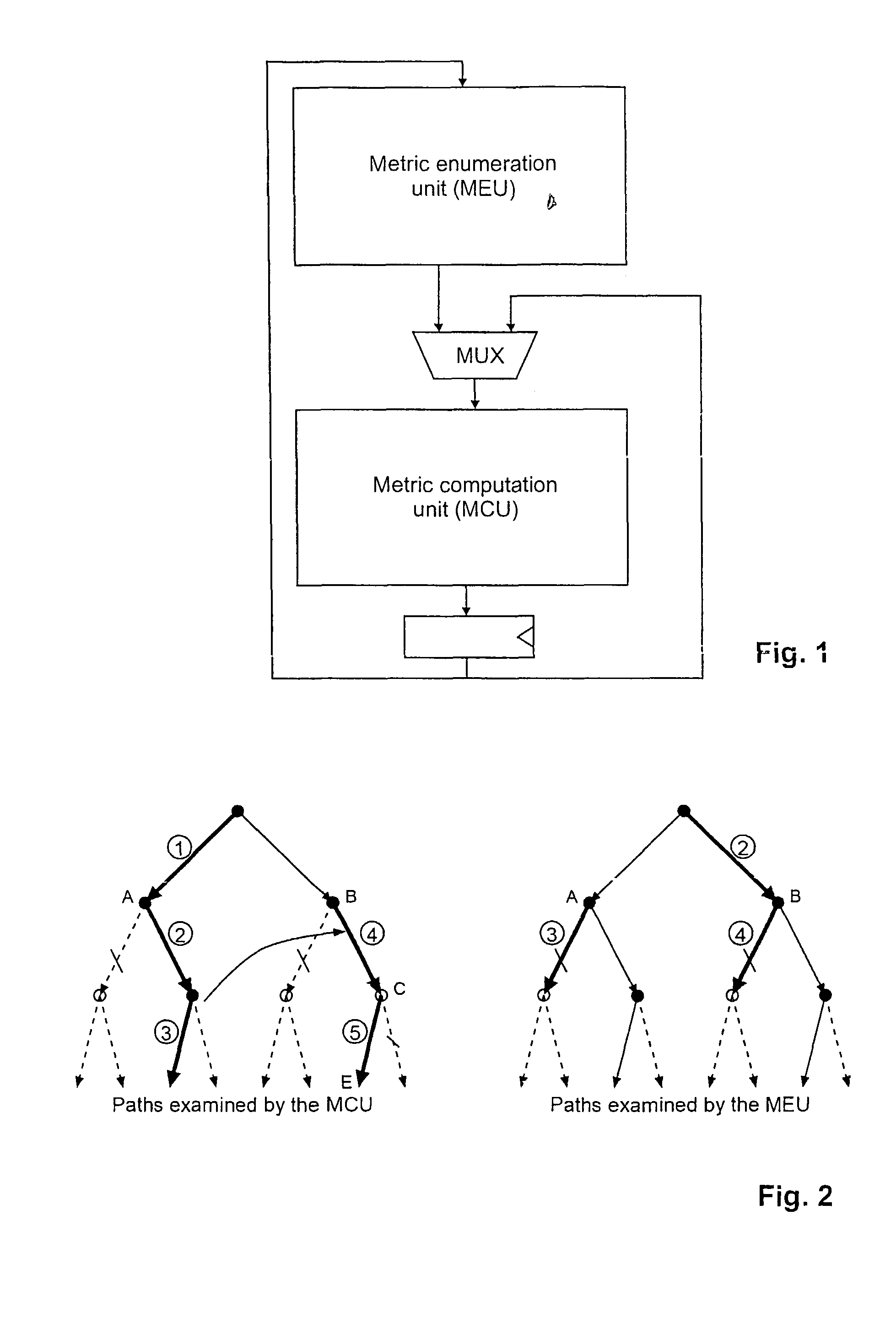
[0159]The second, particularity advantageous embodiment of a device for decoding a received signal in a multiple input / multiple output system also uses the general design of FIG. 1 with a more explicit (i.e., more obvious) separation of MEU and MCU, which carry out a depth-first tree traversal. It uses a decoding scheme as illustrated by FIG. 2. A more detailed block diagram of the circuit is shown in FIG. 10.

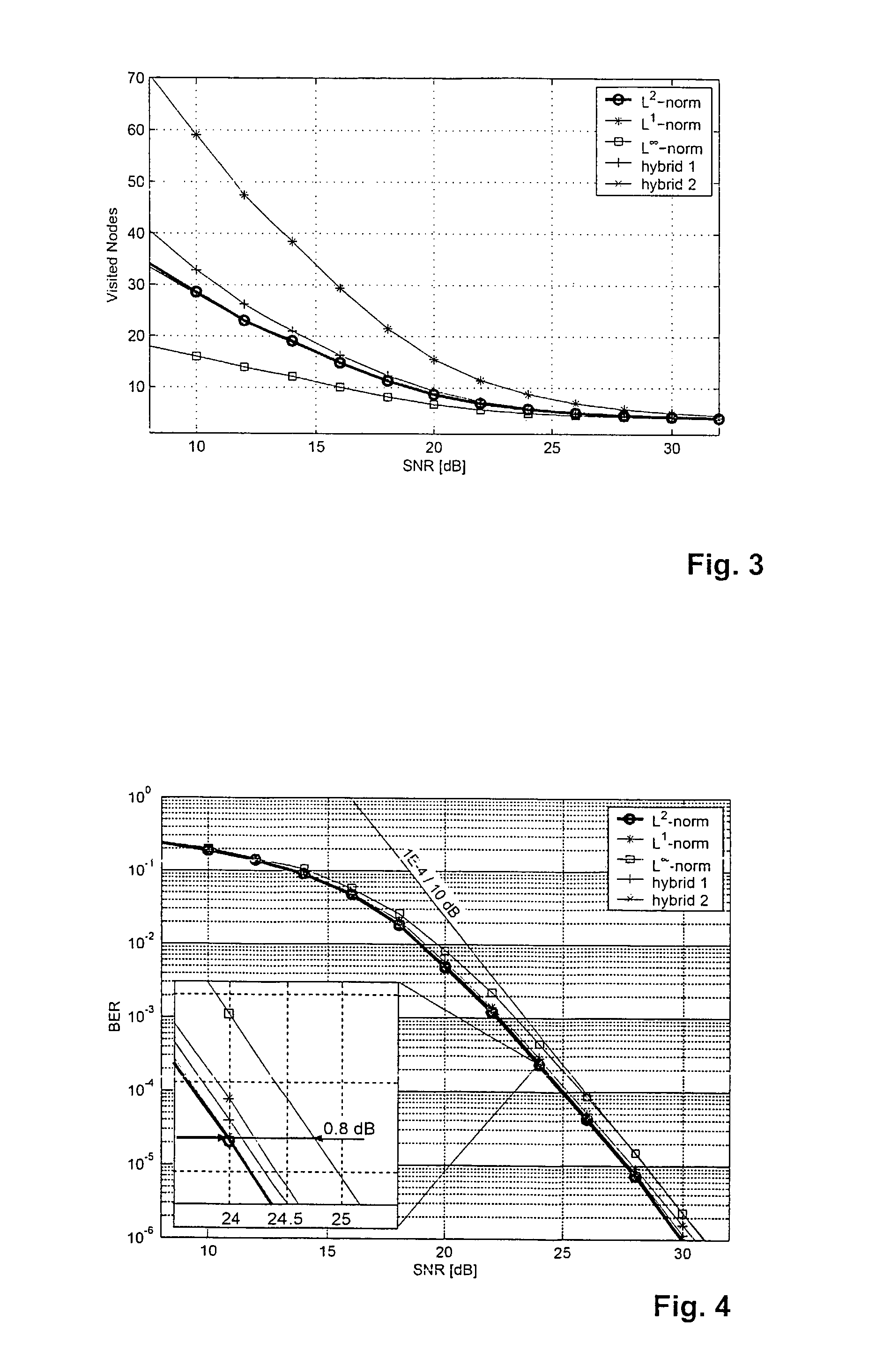
[0160]The second embodiment also adopts the one-node-per-cycle architecture. However, it computes ŷ using ŷ=QHy and employs the l∞-norm approximation as well as a scheme for direct SE enumeration (described below) in systems with QAM modulation.

[0161]A. Direct SE Enumeration for PSK-Like Constellations

[0162]In [11], Hochwald and ten Brink proposed a scheme that allows to compute boundaries of admissible intervals for complex-valued constellations having the constellation points arranged on concentric circles (e.g., PSK, 16-QAM). However, the original propos...


PUM


Abstract

The method for decoding a received signal in a multiple input / multiple output system uses QR-decomposition of the linear channel matrix, but then applies a non-Euclidean norm during tree traversal. Two separate hardware units, namely an MCU and a MEU, art provided for concurrent operation. The MCU determines a next child node, while the MEU determines next best parent nodes on the previously processed tree levels, which makes it possible to retrace the path to a next starting node without investing dedicated processing steps (e.g., cycles). On each tree level, the possible coordinates are grouped into several circular sets in the complex plane, and a series of decision boundaries is calculated for each set that allows a quick evaluation of the optimum coordinate in each set.

Description

CROSS REFERENCES TO RELATED APPLICATIONS[0001]This application claims the priority of U.S. patent application 60 / 610,584, filed 16 Sep. 2004, the disclosure of which is incorporated herein by reference in its entirety.TECHNICAL FIELD[0002]The invention relates to methods and devices for decoding a received signal in a multiple input / multiple output system having linear and noisy transmission characteristics.BACKGROUND ART[0003]Many problems in mobile communications can be described with a simple linear multiple-input multiple-output (MIMO) model. Examples include multiantenna systems or multiuser detection in CDMA. The transmission characteristics of such systems can usually be modeled, at least in approximation, by the equationy=Hs+n,  (1)wherein[0004]y is an N×1 vector describing a received signal,[0005]H is a channel matrix, wherein H=QR with an M×M upper triangular matrix R and an N×M unitary matrix Q,[0006]s a transmitted M×1 signal vector whose coordinate values are chosen fro...

Claims


Application Information

Patent Timeline
Patent Type & Authority Patents(United States)
IPC IPC(8): H04B7/02
CPCH04L1/0656H04L25/03203H04L25/03242
Inventor BURG, ANDREASBORGMANN, MORITZWENK, MARKUSZELLWEGER, MARTIN
Owner ETH ZZURICH
Learn More