
Telescopic pipe support system

Inactive Publication Date: 2010-08-24
HERBERS CHARLES R
View PDF13 Cites 9 Cited by
  • Summary
  • Abstract
  • Description
  • Claims
  • Application Information

AI Technical Summary

Benefits of technology

[0020]It is another object of the present invention to provide a pipe support system being easily and quickly mounted atop and below wood flooring or concrete decking.
[0021]It is another object of the present invention to provide a lightweight and rigid pipe support system.
[0023]It is another object of the present invention to provide a pipe support system which provides user with a multitude of telescopic adjustment capabilities.
[0025]It is another object of the present invention to provide hanger elements being quickly and easily attached to the shaft in order to allow for quick and easy support of construction articles such as pipes.
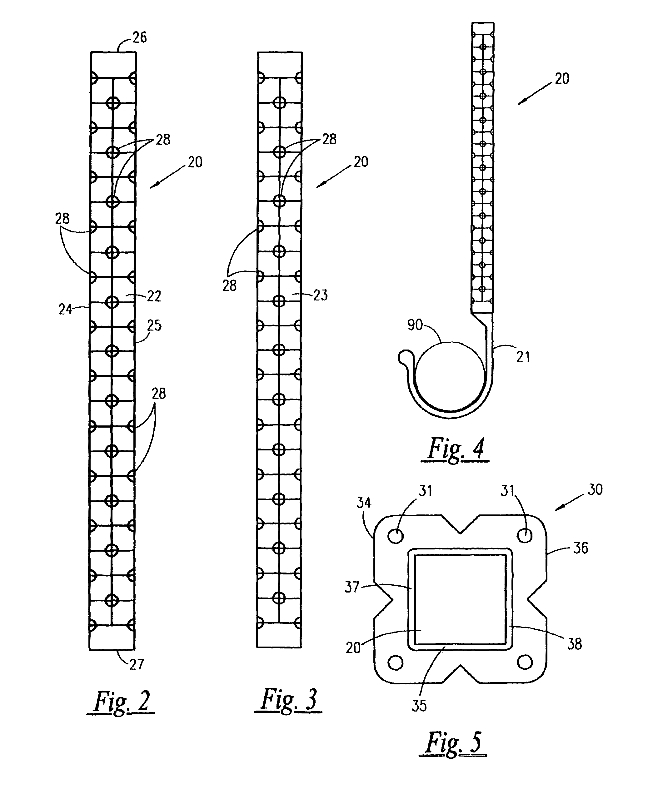
[0030]A generally square-shaped central opening is formed within the planar base which provides entrance into a shaft receiving cavity. A pair of springpin receiving cavities are formed approximately midway about sidewalls of body portion. The springpin receiving cavities jointly define a t-shaped configuration. The planar base includes an aperture formed in each quadrant thereof, through which a nail is intended to be driven. An outwardly-biased springpin is suitably disposed perpendicularly through shaft, just below the top end thereof. The top end of shaft is inserted through a concrete opening, through central opening of planar base, and into the shaft receiving cavity, where shoulders of springpin engage the inner sidewalls of body portion facilitating contraction of springpin until reaching springpin receiving cavities, whereupon springpin protracts therein in an enclosing relationship, and thereby removably securing shaft within auxiliary anchor.
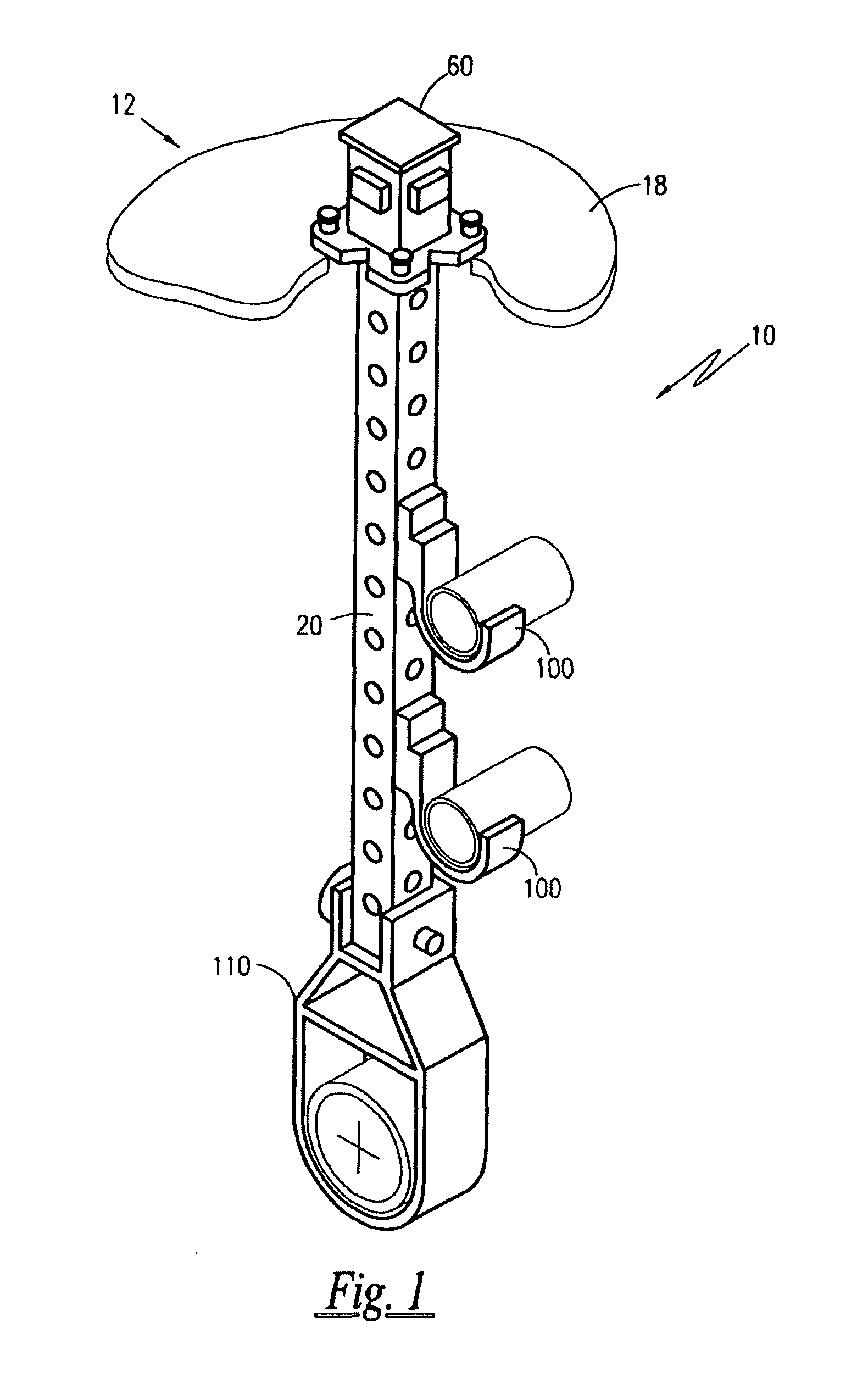
[0032]A clevis hanger is disclosed and adapted for removable attachment to the open bottom end of shaft. Attachment of clevis hanger to shaft is facilitated through the use of a pin.

Problems solved by technology

In the construction industry, buildings and passages such as roadways and bridges which utilize poured concrete construction and wood pose particular problems when installing deck anchors for supporting a variety of fixtures such as safety cable, piping, ductwork, lighting, and other construction materials.
However, the prior art has failed to address the need for a lightweight pipe support system which can be quickly and easily installed in concrete or wood, which is telescopic, and which allows for a multitude of construction articles to be supported in a vertically-oriented, space-saving manner.

Method used


Image

  • Telescopic pipe support system
  • Telescopic pipe support system
  • Telescopic pipe support system

Examples


Embodiment Construction

1. Detailed Description of the Figures

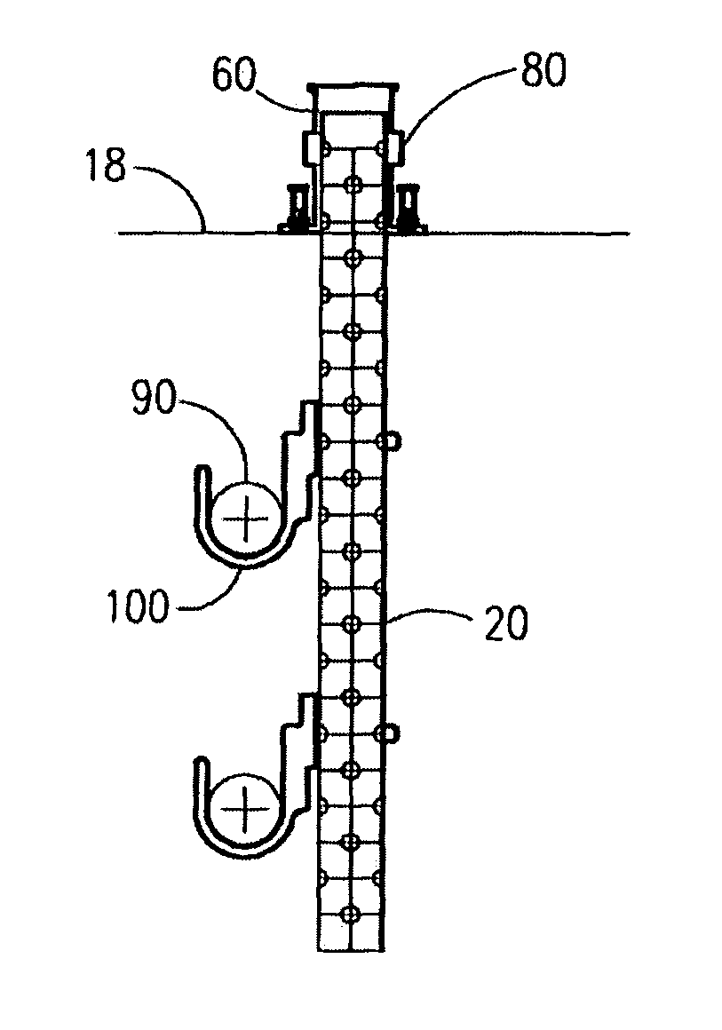
[0052]Referring now to FIGS. 1-7, a telescopic pipe support system 10 is shown, according to the present invention, adapted to support a plurality of pipes 90.

[0053]The telescopic pipe support system 10 is further adapted to be mounted atop and below flooring 12, wherein flooring 12 includes but is not limited to wood 15 and concrete 18. The telescopic pipe support system 10 is comprised of an elongated tubular shaft 20 having a generally square configuration. The shaft 20 is constructed of a suitably rigid material, for example metal; or a thermoplastic polymer, preferably, polyvinylchloride. The shaft 20 defines a front vertical wall 22 opposing a rear vertical wall 23, a right vertical wall 24 opposing a left vertical wall 25, and an open top end 26 opposing an open bottom end 27. The front vertical wall 22 and the rear vertical wall 23 include a plurality of foramens 28 extending therethrough and vertically aligned along an elongated centerl...


PUM


Abstract

A telescopic pipe support system is provided for supporting a plurality of pipes. The pipe support system utilizes an elongated, tubular shaft adapted to be mounted atop and below wood flooring as well as below concrete decking via a shaft receiving anchor and an auxiliary anchor, respectively. Hanger elements are removably attached along various longitudinal positions of the shaft in order to quickly and easily support construction articles.

Description

RELATED APPLICATIONS[0001]The present invention is a divisional application of U.S. patent Ser. No. 10 / 962,815 filed on Oct. 12, 2004 now abandoned, incorporated by reference herein.BACKGROUND OF THE INVENTION[0002]1. Field of the Invention[0003]The present invention relates generally to deck anchors and, more particularly, to a telescopic pipe support system.[0004]2. Description of the Related Art[0005]In the construction industry, buildings and passages such as roadways and bridges which utilize poured concrete construction and wood pose particular problems when installing deck anchors for supporting a variety of fixtures such as safety cable, piping, ductwork, lighting, and other construction materials. In buildings using poured concrete decking, each floor is built by constructing frameworks of columns, posts, jacks, and horizontal beams on a lower floor, and laying flooring atop such lower flooring, and often pouring concrete there atop so as to form a reinforced concrete floor...

Claims


Application Information

Patent Timeline
IPC IPC(8): E21F17/02
CPCE21F17/02H02G3/263H02G3/30
Inventor HERBERS, CHARLES R.
Owner HERBERS CHARLES R
Learn More