
Fuel injection control apparatus for internal combustion engine

a technology of control apparatus and fuel injection, which is applied in the direction of electrical control, brake systems, instruments, etc., can solve the problems of increasing the frequency of resumption of fuel injection, affecting the accuracy of fuel injection, and changing the delay of valve closing, so as to achieve accurate opening and closing

Inactive Publication Date: 2010-08-17
HITACHI LTD
View PDF5 Cites 4 Cited by
  • Summary
  • Abstract
  • Description
  • Claims
  • Application Information

AI Technical Summary

Benefits of technology

[0008]In recent years, reduction in the idling speeds of internal combustion engines in terms of reduction in fuel consumption rate has been required and a demand for the minimum quantity of fuel injectable from fuel injectors tends to be decreasing. Likewise, for reduction in fuel consumption rate, the chances of fuel cuts for not injecting the fuel when the output of the internal combustion engine is unnecessary are increasing, which, in turn, is also increasing the frequency of resumption of fuel injection. Resuming fuel injection requires injecting a small quantity of fuel equivalent to a no-load state. Also, split injection is used for increased output and / or for improved exhaust performance. Split injection is intended to improve the performance of the internal combustion engine by injecting timely in multiple split shots the necessary quantity of fuel to be originally injected in one shot. During split inspection, the fuel injection quantity per shot may be required to be reduced.
[0011]An object of the present invention is to provide a fuel injection control apparatus for an internal combustion engine, capable of opening and closing accurately a valve of the fuel injector even when the quantity of injection required is small and a pulse duration of a driving pulse signal to the fuel injector is short.
[0014]Because of the above system configuration, the valve of the fuel injector can be opened and closed accurately, even when the injection quantity required is small and a duration of power distribution (i.e., the pulse width of the pulse signal) to the fuel injector is short.
[0022]Because of the above system configuration, the valve of the fuel injector can be opened and closed accurately, even when the injection quantity required is small and a duration of power distribution (i.e., the pulse width of the pulse signal) to the fuel injector is short.
[0025]According to the present invention, the valve of the fuel injector can be opened and closed accurately, even when the quantity of injection required is small and the pulse duration of the driving pulse signal to the fuel injector is short.

Problems solved by technology

Likewise, for reduction in fuel consumption rate, the chances of fuel cuts for not injecting the fuel when the output of the internal combustion engine is unnecessary are increasing, which, in turn, is also increasing the frequency of resumption of fuel injection.
Any errors in the valve-closing delay, therefore, directly affect the accuracy of the injection quantity very significantly.
In addition, the valve-closing delay changes with the response delay of the electric circuit.
This change in the valve-closing delay has caused the injector valve-opening delay to vary according to the particular flow state of the current through the injector, in the termination timing of power distribution thereto, and the variation has impeded the improvement of the internal combustion engine in performance.
Although the methods described in JP-3562125, JP-A-2003-65129, JP-3768723, and JP-3768723 are effective for improving the valve-opening delay and the valve-closing delay, none of the methods has sufficed to reduce the minimum quantity of injection required.

Method used


Image

  • Fuel injection control apparatus for internal combustion engine
  • Fuel injection control apparatus for internal combustion engine
  • Fuel injection control apparatus for internal combustion engine

Examples


first embodiment

[0037]The configuration and operation of a fuel injection control apparatus for an internal combustion engine according to the present invention will be described hereunder using FIGS. 1 to 7.

[0038]First, an internal combustion engine system configuration with the fuel injection control apparatus for an internal combustion engine according to the first embodiment of the present invention will be described using FIG. 1.

[0039]FIG. 1 is a block diagram of the internal combustion engine system with the internal combustion engine fuel injection control apparatus according to the first embodiment of the present invention.

[0040]The engine 1 includes a piston 2, an air suction valve 3, and an exhaust valve 4. Suction air is passed through an air flowmeter (AFM) 20, then enters a throttle valve 19, and supplied from a collector 15 that is a branch section, through an air suction pipe 10 and the suction valve 3 to a combustion chamber 21 of the engine 1. Fuel is supplied from a fuel tank 23 t...

second embodiment

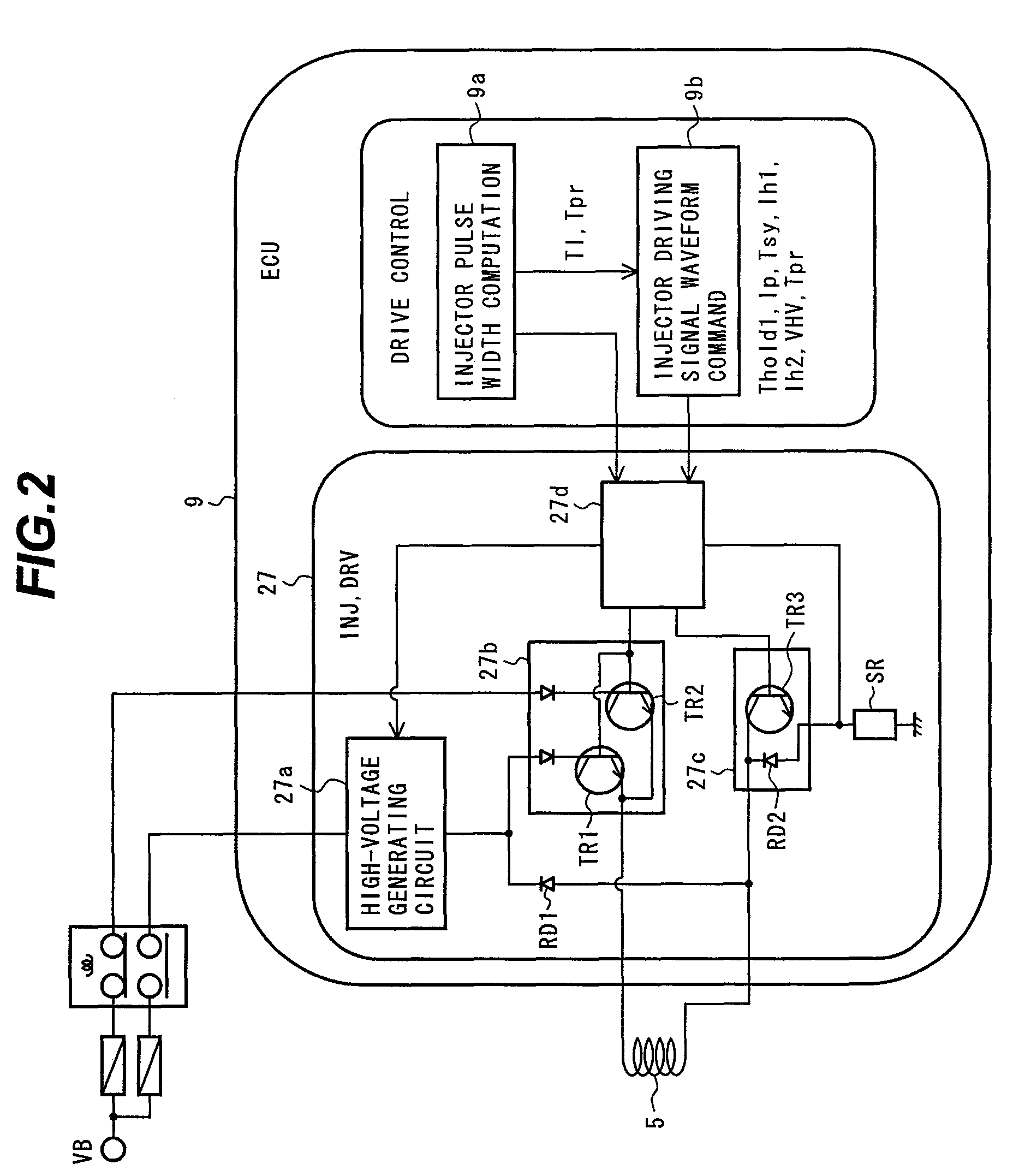
[0114]The configuration and operation of a fuel injection control apparatus for an internal combustion engine according to the present invention will be described hereunder using FIG. 8. The description assumes that an internal combustion engine system configuration with the internal combustion engine fuel injection control apparatus according to the present embodiment is essentially the same as the system configuration shown in FIG. 1. The description also assumes that the configuration of the internal combustion engine fuel injection control apparatus according to the present embodiment is essentially the same as the system configuration shown in FIG. 2. In addition, the description assumes that the operation of the internal combustion engine fuel injection control apparatus, achieved in the present embodiment when the fuel injection pulse width is large, is essentially the same as the system configuration shown in FIG. 3. Furthermore, the description assumes that control by the i...

third embodiment

[0131]The configuration and operation of a fuel injection control apparatus for an internal combustion engine according to the present invention will be described hereunder using FIG. 9. The description assumes that an internal combustion engine system configuration with the internal combustion engine fuel injection control apparatus according to the present embodiment is essentially the same as the system configuration shown in FIG. 1. The description also assumes that the configuration of the internal combustion engine fuel injection control apparatus according to the present embodiment is essentially the same as the system configuration shown in FIG. 2. In addition, the description assumes that the operation of the internal combustion engine fuel injection control apparatus, achieved in the present embodiment when the fuel injection pulse width is large, is essentially the same as the system configuration shown in FIG. 3. Furthermore, the description assumes that control by the i...


PUM


Abstract

A fuel injection control apparatus includes a computing unit that calculates a pulse width for a pulse signal which drives the valve of a fuel injector, based on the operational state of the internal combustion engine and fuel pressure detected by a fuel pressure sensor. After a valve-opening command has turned on and a high valve-opening current has been supplied to open the fuel injector valve, a fuel injector driving signal waveform command unit discharges the current and supplies a small hold current Ih2 to maintain the injector's valve-open state. After the elapse of a predetermined rapid-discharge starting time from the turn-on of the valve-opening command, the fuel injector driving signal waveform command unit rapidly discharges the current until the hold current Ih2 has been reached.

Description

BACKGROUND OF THE INVENTION[0001]1. Field of the Invention[0002]The present invention relates generally to fuel injection control apparatus for internal combustion engines. More particularly, the invention concerns a fuel injection control apparatus for an internal combustion engine, capable of improving a minimum fuel injection quantity.[0003]2. Description of the Related Art[0004]Internal combustion engines are equipped with a fuel injection control apparatus that computes an appropriate fuel injection quantity according to the particular operational state of the engine and drives a fuel injector for supplying a fuel. The fuel injector opens or closes a valve constituting the injector, by utilizing the magnetic force generated by a built-in coil energized with the electric current allowing the injector to open the valve and to retain this open state, and thus injects the amount of fuel that is appropriate for the particular opening duration of the valve. The quantity of fuel injec...

Claims


Application Information

Patent Timeline
Patent Type & Authority Patents(United States)
IPC IPC(8): B60T7/12F02M1/00
CPCF02D41/20F02D2041/2003F02D2041/2044F02D2200/0602
Inventor TOYOHARA, MASAHIROMIYAKE, TAKAOSASAKI, MASAHIROMAYUZUMI, TAKUYA
Owner HITACHI LTD
Learn More