
Device for heating grounds, in particular sports ground

Inactive Publication Date: 2010-08-17
DERMOPTICS +1
View PDF7 Cites 0 Cited by
  • Summary
  • Abstract
  • Description
  • Claims
  • Application Information

AI Technical Summary

Benefits of technology

"The present invention proposes a device for heating sports grounds in a safe and efficient way. The device uses cables buried in the soil and connected to a transformer. The surface of the ground is divided into sectors, each sector being heated by at least two heating lines. The transformer is preferably a torus type, with a secondary winding made in a metal with lower conductivity than the heating lines. The diameter of the wire of the secondary winding and that of the heating lines are identical to facilitate connection problems. The transformers are placed close to the ground to maximize power efficiency. The primary winding of the transformers may have a shield made of metal sheet. The cable forming the secondary winding of the transformer may be made in two conducting components twisted over each other. The invention allows for efficient heating of grounds while saving energy and reducing costs."

Problems solved by technology

In this way, the diameter of the wire of the secondary winding and that of the heating line may thus have identical diameters which notably facilitate connection problems.

Method used


Image

  • Device for heating grounds, in particular sports ground
  • Device for heating grounds, in particular sports ground
  • Device for heating grounds, in particular sports ground

Examples


Embodiment Construction

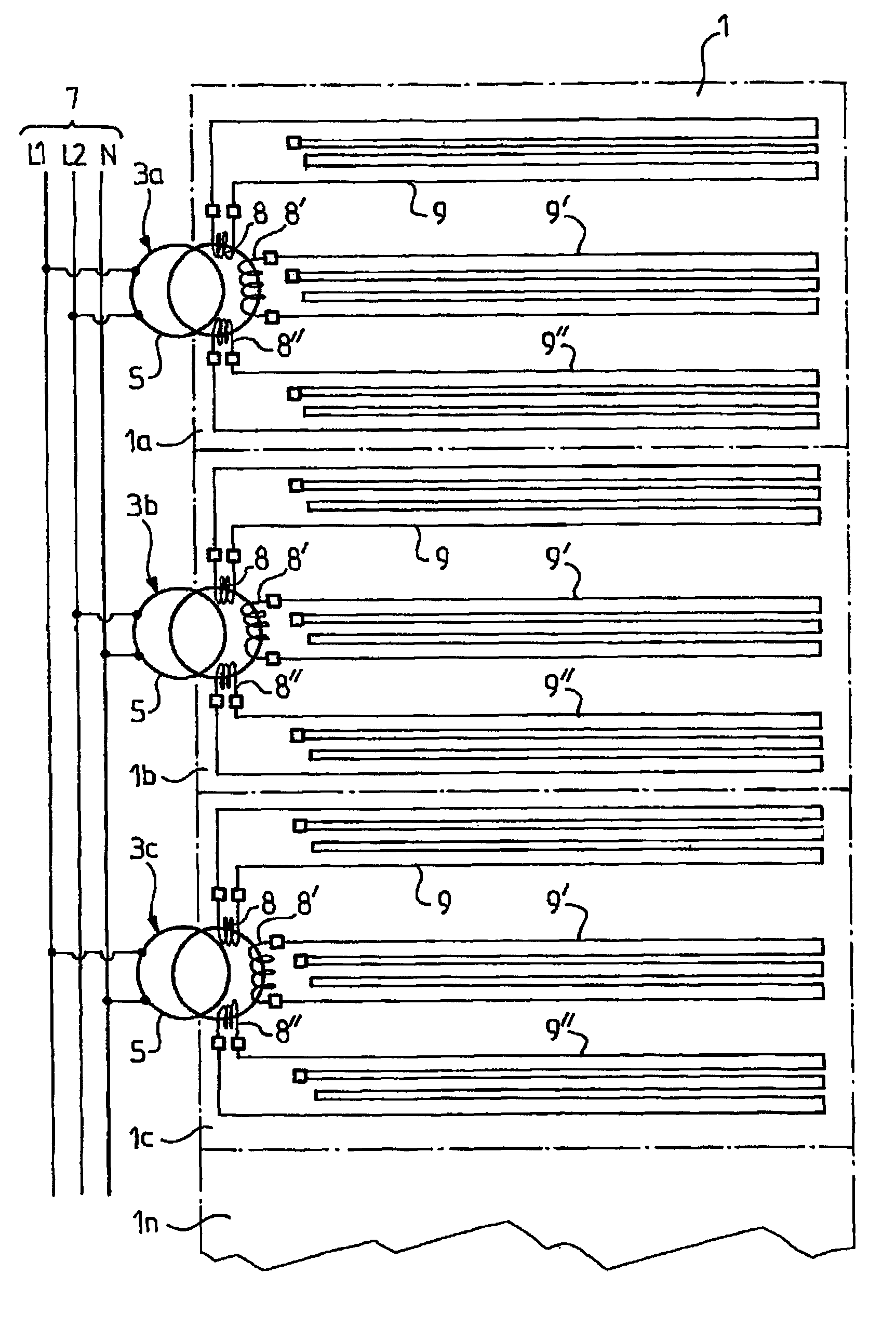
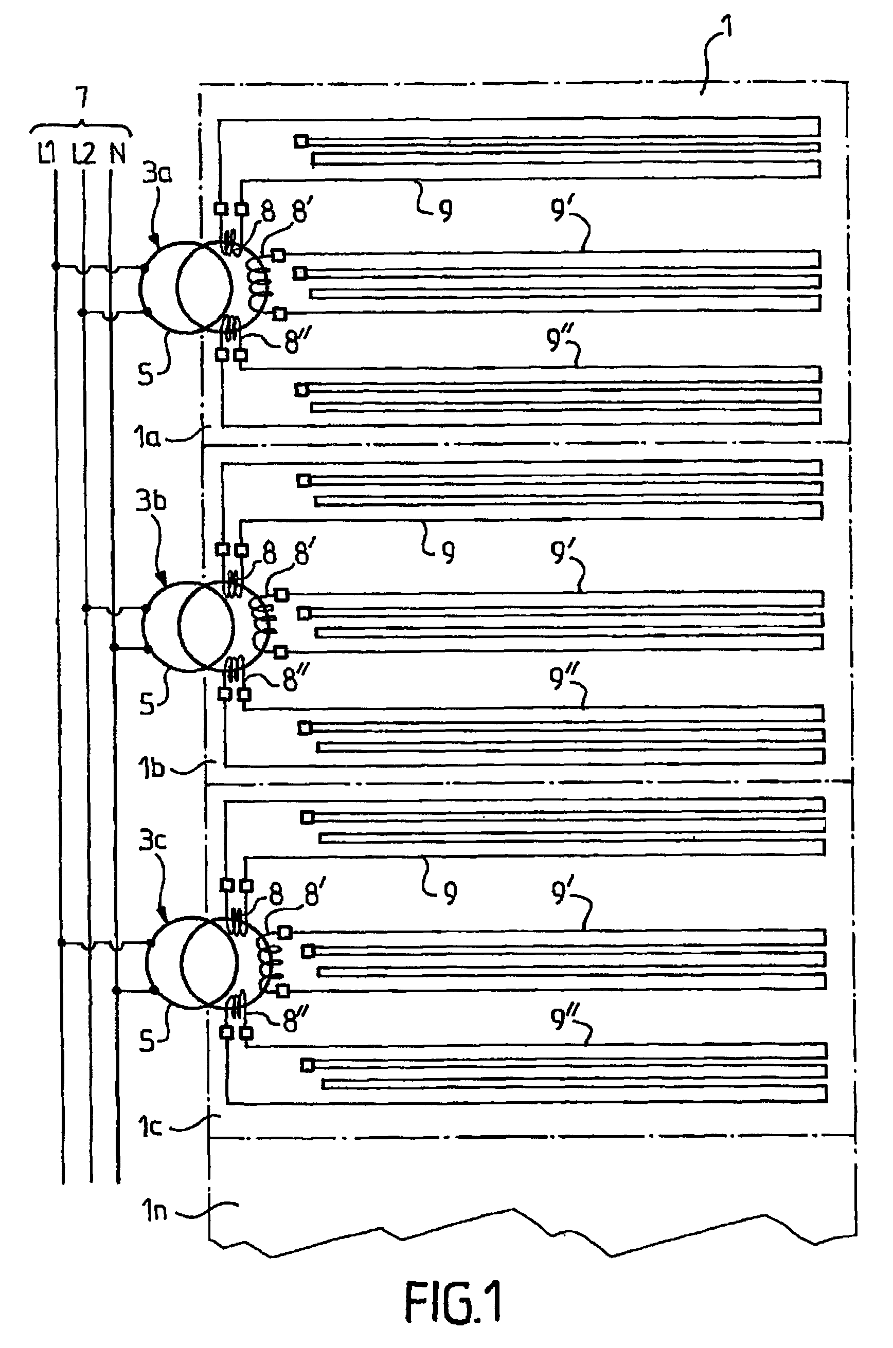
[0018]A portion of a sports ground 1 which is divided in several sectors, i.e., sectors 1a, 1b, 1c which are intended to be heated so as to keep them frost-free, for example, is illustrated in FIG. 1.

[0019]The heating installation consists of a series of transformers 3a, 3b, 3c, . . . , 3n which are each associated with the heating of a determined ground sector 1a, 1b, 1c, . . . , 1n. A transformer thus for example, provides the power supply for three heating lines, 9, 9′, 9″ of a determined sector, these heating lines being buried into the soil of each of these sectors, and being either distributed uniformly or not in the space of the sectors, and this depending on the calorific needs of each of the latter.

[0020]More specifically, the primary 5 of each of these transformers is powered by a three-phase electric line 7 formed with two phase lines L1, L2 and a neutral line N. Conventionally, and in order not to unbalance the installation, the three primary windings of the transformers...


PUM


Abstract

An installation for heating grounds, in particular sports grounds, using cables (9, 9′, 9″) supplied with electric current which are buried in the ground. The installation is characterized in that the surface of the grounds to be heated is divided into a number of sectors (1a, 1b, 1c, . . . , 1n), and each sector is heated by at least two heating lines (9, 9′, 9″) constituting each a secondary of a common transformer (3a, 3b et 3c).

Description

BACKGROUND OF THE INVENTION[0001]The present invention relates to a device for providing the heating of grounds and notably for keeping sports grounds frost-free.DETAILED DESCRIPTION OF THE RELATED ART[0002]Such heating devices are known and to do this, they resort to conducting cables which are buried in the ground and which are supplied with electric current via transformers which are placed in a plantroom neighbouring the ground to be heated. The latter is subdivided into several sectors dug with trenches in which the heating cables connected to the secondary circuit of the transformer are placed.[0003]The devices for heating grounds of this type have a major drawback in that the electric power is transported from the transformer to the sector to be heated by power connections which, upon use, prove to be extremely costly in the amount of consumed power on the one hand, and in raw material cost on the other hand. Moreover, in this type of installation, all the sectors intended to...

Claims


Application Information

Patent Timeline
Patent Type & Authority Patents(United States)
IPC IPC(8): A45D20/40H05B3/20H05B3/40H05B6/02
CPCH05B3/56H05B2203/026H05B3/20H05B3/40E01C13/02E01C13/083
Inventor SCHERRER, JEAN-MARCSCHERRER, JEAN-PAULBEISSER, JEAN-CLAUDE
Owner DERMOPTICS
Learn More