
Thermostatic valve having anti-siphon feature

a technology of thermostatic valve and feature, which is applied in the direction of fluid pressure control, process and machine control, instruments, etc., can solve the problems of fuel module malfunction, fuel pressure drop to undesirable levels, etc., and achieve the effect of reducing the required packaging envelope and removing/reducing the fuel from the system

Active Publication Date: 2018-12-04
VITESCO TECH USA LLC
View PDF23 Cites 1 Cited by
  • Summary
  • Abstract
  • Description
  • Claims
  • Application Information

AI Technical Summary

Benefits of technology

Effectively prevents fuel from escaping the system by maintaining pressure within the fuel module, even if return fuel lines are compromised, and can be retrofitted into existing applications with minimal packaging impact.

Problems solved by technology

However, if any of the conduits or other components in the return system become compromised, such as disconnected or broken, the pressure in the return system may drop to undesirable levels, and cause the fuel module to malfunction.

Method used


Image

  • Thermostatic valve having anti-siphon feature
  • Thermostatic valve having anti-siphon feature
  • Thermostatic valve having anti-siphon feature

Examples


Embodiment Construction

[0021]The following description of the preferred embodiment(s) is merely exemplary in nature and is in no way intended to limit the invention, its application, or uses.

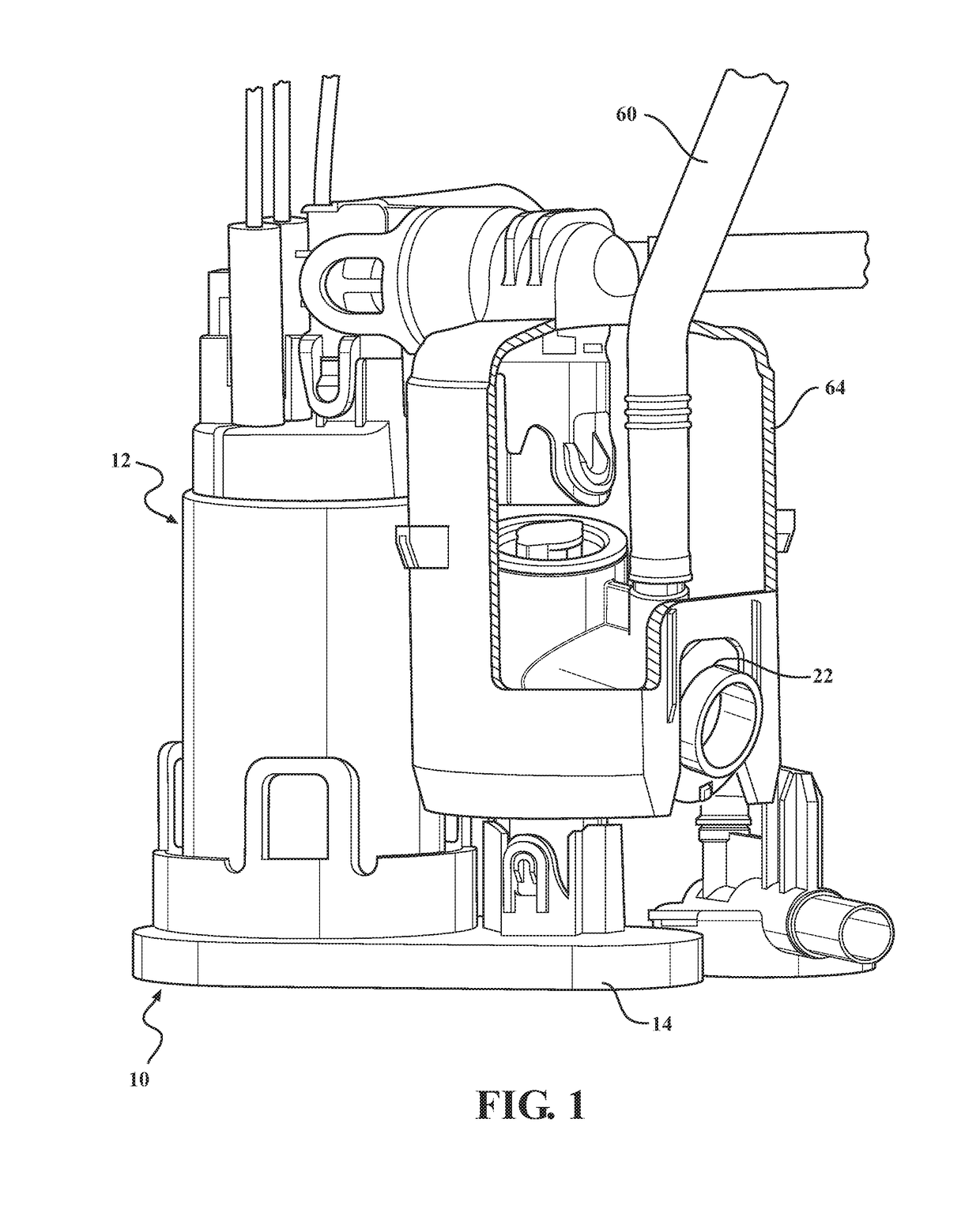
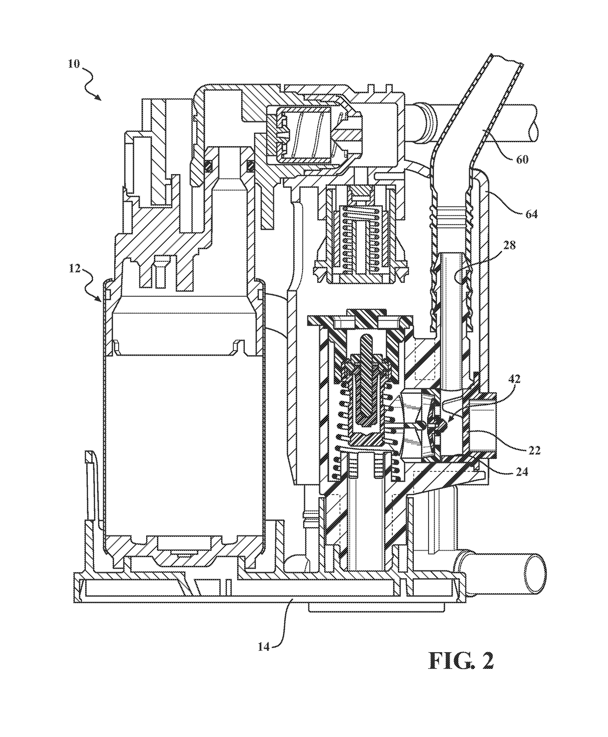
[0022]A first embodiment of a fuel module having a thermostatic valve assembly according to the present invention is shown in FIGS. 1-2, generally at 10. The module 10 includes a pump assembly, shown generally at 12, having an electric motor, and a pumping mechanism, shown generally at 16. The pumping mechanism 16 may be any type of pumping mechanism capable of transferring fluid, which in this embodiment is an impeller pump. Connected to the pump assembly 12 is a fuel filter 14, and also connected to the fuel filter 14 is a housing 18, which is part of an inner assembly, shown generally at 20.

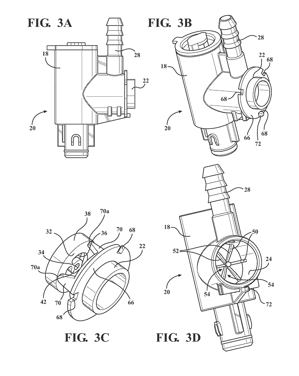
[0023]Referring to FIGS. 3A-3E, the assembly 20 also includes an anti-siphon valve 22 located in a cavity, shown generally at 24, formed as part of the housing 18. The valve 22 includes a cavity, shown generally at 25, formed as...


PUM


Abstract

A thermostatic valve, which includes a main body portion, a cavity formed as part of a main body portion, and an inner wall integrally formed with the main body portion adjacent the cavity. A circumferential flange is integrally formed with the inner wall, such that the circumferential flange surrounds a valve cavity. A valve member is attached to the inner wall disposed in the valve cavity, and a flow aperture is formed as part of the inner wall. Fluid flows through the flow aperture into the valve cavity, and when the pressure in the valve cavity is above a predetermined value, the valve member contacts the inner wall, preventing fluid from flowing through the flow aperture.

Description

CROSS-REFERENCE TO RELATED APPLICATIONS[0001]This application claims the benefit of U.S. Provisional Application No. 62 / 213,463 filed Sep. 2, 2015. The disclosure of the above application is incorporated herein by reference.FIELD OF THE INVENTION[0002]The invention relates generally to a valve for a fuel module used for preventing backflow when an undesirable pressure drop occurs.BACKGROUND OF THE INVENTION[0003]Fuel modules are commonly known, and are used for transferring fuel from a fuel tank to an engine. Several of these types of fuel modules have a return system, where fuel that is not consumed by the engine is returned to the fuel tank. These return systems typically operate at a certain pressure, typically less than 50 kPa. However, if any of the conduits or other components in the return system become compromised, such as disconnected or broken, the pressure in the return system may drop to undesirable levels, and cause the fuel module to malfunction.[0004]Accordingly, ther...

Claims


Application Information

Patent Timeline
Patent Type & Authority Patents(United States)
IPC IPC(8): F16K15/14F02M37/10F16K31/00G05D16/06F02M37/00
CPCG05D16/0636F02M37/0023F02M37/0035F16K15/148F16K31/002F02M37/106Y10T137/789
Inventor POWERS, MICHAELBEEMER, ERINWATTAI, JOHN
Owner VITESCO TECH USA LLC
Learn More