Plastic rod lens, rod lens array, rod lens plate, image sensor and printer
a technology of plastic rods and lenses, applied in the direction of lenses, optical elements, instruments, etc., can solve the problems of not having a specific description of the plastic rod lens with difficult to obtain a plastic rod lens having a small chromatic aberration, and difficult to apply the technique to the manufacturing process of plastic rod lenses. achieve the effect of small chromatic aberration, excellent color characteristics and high resolution
- Summary
- Abstract
- Description
- Claims
- Application Information
AI Technical Summary
Benefits of technology
Problems solved by technology
Method used
Image

Examples
example 1
[0176]Stock solutions for each layer were prepared as shown in Table 2 below.
[0177]
TABLE 2Composition of stockPhysical properties after curingsolution (% by mass)RefractivePMMAMMATDMABzMA8FMindex nAbbe number vKKmax. − Kmin.Ex. 1First layer462430——1.50255.7166.661.90Second layer462915551.49754.7164.76Third layer4937—681.49054.8166.64Fourth layer4723—10201.48454.2166.18Fifth layer393—17411.47253.2165.91Comp. Ex. 1First layer472330——1.50255.7166.6619.65Second layer504010——1.49655.9168.60Third layer5040——101.48556.6173.30Fourth layer5040——101.48556.6173.30Fifth layer4218——401.46058.7186.31Each layer contains 0.25% by mass of a photo-curing catalyst and 0.1% by mass of HQ.K = n · v / (n − 1), Kmax. = maximum value among the values of K in the first to fifth layers, and Kmin. = minimum value among the values of K in the first to fifth layers.
[0178]Note that in order to suppress crosstalk light or flare light, a dye Blue ACR (manufactured by Nippon Kayaku Co., Ltd.), a dye Blue 4 G (manufac...
example 2
[0197]A plastic rod lens was manufactured as in Example 1 except that the draw ratio and the relaxation rate were changed to 3.50-fold and 500 / 700, respectively.
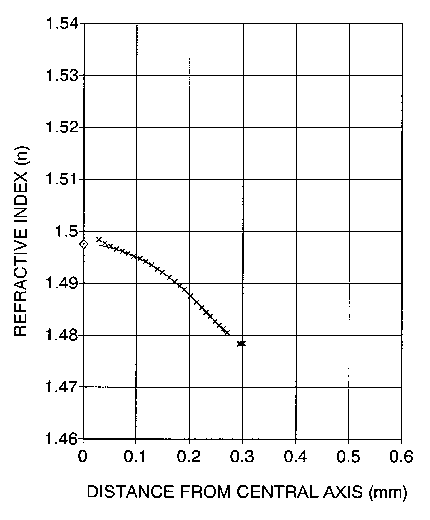
[0198]The radius R of the obtained plastic rod lens was 0.187 mm and the central refractive index was 1.497. The refractive index distribution within the distance range of 0.2 R to 0.8 R from the central axis towards the outer peripheral portion approximated to the following formula (5), and the refractive index distribution constant g at a wavelength of 525 nm was 0.84 mm−1.
[0199]Then a rod lens array was manufactured as in Example 1 except that the interval between the plastic rod lenses was changed from 0.37 mm to 0.39 mm, and the adhesive was changed from Araldite rapid to “Esudain 9607K” manufactured by Sekisui Fuller Co., Ltd. The conjugation length Tc of this rod lens array at 525 nm was 10.0 mm and MTF at this time point was 72.6%.
[0200]Tc values of this rod lens array at each wavelength of 470 nm, 525 nm, and 630 nm...
example 3
[0201]A plastic rod lens and a rod lens array were manufactured as in Example 2 except that the amount of dyes added in the fourth layer was changed as shown in the following Table 5.
[0202]
TABLE 5DyeFourth layer (% by mass)Blue ACR0.003Blue 4G0.003MS Magenta HM-14500.003MS Yellow HD-1800.006KAYASORB CY-100.003
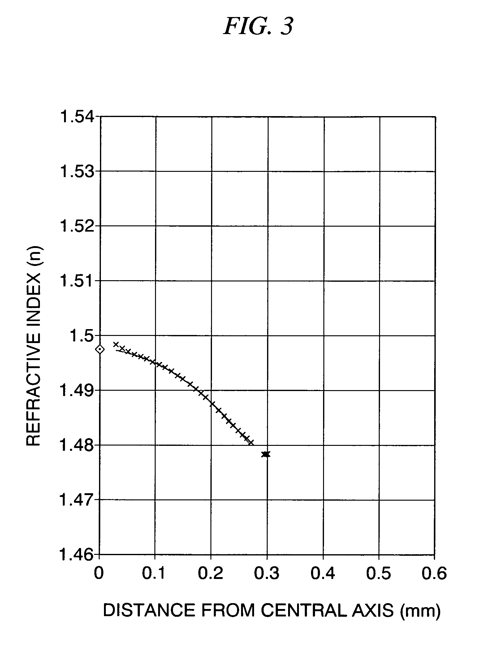
[0203]The radius R of the obtained plastic rod lens was 0.187 mm and the central refractive index was 1.497. The refractive index distribution within the distance range of 0.2 R to 0.8 R from the central axis towards the outer peripheral portion approximated to the formula (5), and the refractive index distribution constant g at a wavelength of 525 nm was 0.84 mm−1.
[0204]The conjugation length Tc of this rod lens array at 525 nm was 10.0 mm and the MTF at this time point was 62.4%.
[0205]Tc values of this rod lens array at each wavelength of 470 nm, 525 nm, and 630 nm were measured (Table 8). Additionally, when MTFs of the above three wavelengths at a certain Tc were compared, T...
PUM
| Property | Measurement | Unit |
|---|---|---|
| Abbe numbers | aaaaa | aaaaa |
| Abbe number | aaaaa | aaaaa |
| refractive index | aaaaa | aaaaa |
Abstract
Description
Claims
Application Information
 - R&D
- Intellectual Property
- Life Sciences
- Materials
- Tech Scout
- Unparalleled Data Quality
- Higher Quality Content
- 60% Fewer Hallucinations
Browse by: Latest US Patents, China's latest patents, Technical Efficacy Thesaurus, Application Domain, Technology Topic, Popular Technical Reports.
© 2025 PatSnap. All rights reserved.Legal|Privacy policy|Modern Slavery Act Transparency Statement|Sitemap|About US| Contact US: help@patsnap.com