
Array substrate and liquid crystal display panel

An array substrate and display mode technology, applied in the direction of static indicators, optics, instruments, etc., can solve the problems of reduced aperture ratio and display brightness, and achieve the effects of increasing aperture ratio, reducing color distortion, and reducing binocular signal crosstalk

Active Publication Date: 2013-10-16
TCL CHINA STAR OPTOELECTRONICS TECH CO LTD
View PDF3 Cites 24 Cited by
  • Summary
  • Abstract
  • Description
  • Claims
  • Application Information

AI Technical Summary

Problems solved by technology

However, adopting this method will greatly reduce the aperture ratio in the 2D display mode and reduce the display brightness in the 2D display mode.

Method used


Image

  • Array substrate and liquid crystal display panel
  • Array substrate and liquid crystal display panel
  • Array substrate and liquid crystal display panel

Examples


Embodiment Construction

[0022] In liquid crystal display technology, in order to improve color distortion under large viewing angles, in pixel design, a pixel is usually divided into multiple pixel areas with different liquid crystal orientations, and the voltage of each pixel area is controlled to be different, so that the two The liquid crystal molecules in each pixel area are arranged differently, thereby improving the color distortion under large viewing angles, so as to achieve the effect of LCS (Low Color Shift, low color shift), that is, to obtain the effect of small color difference under large viewing angles.

[0023] The present invention will be described in detail below in conjunction with the embodiments and the accompanying drawings.

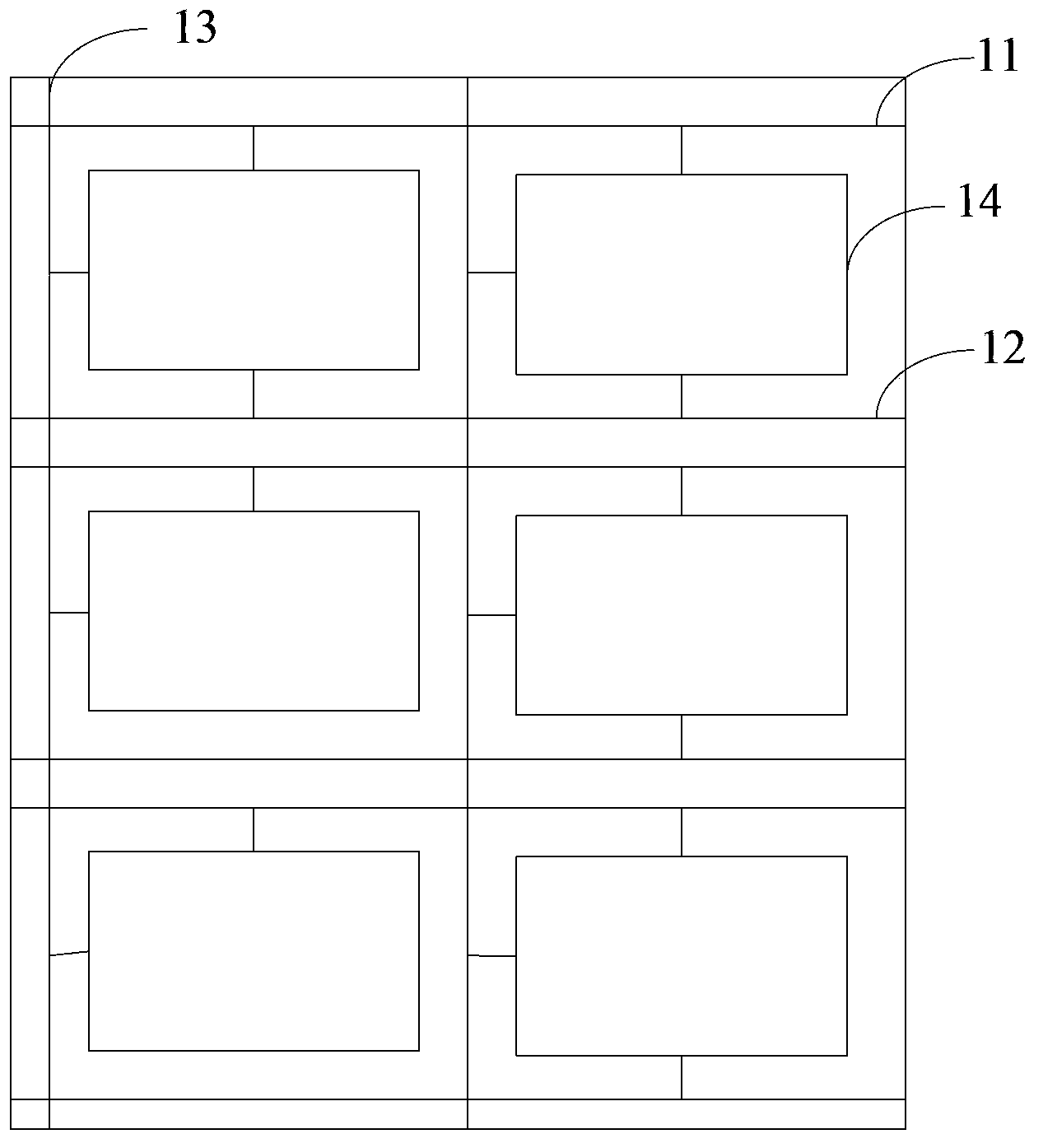
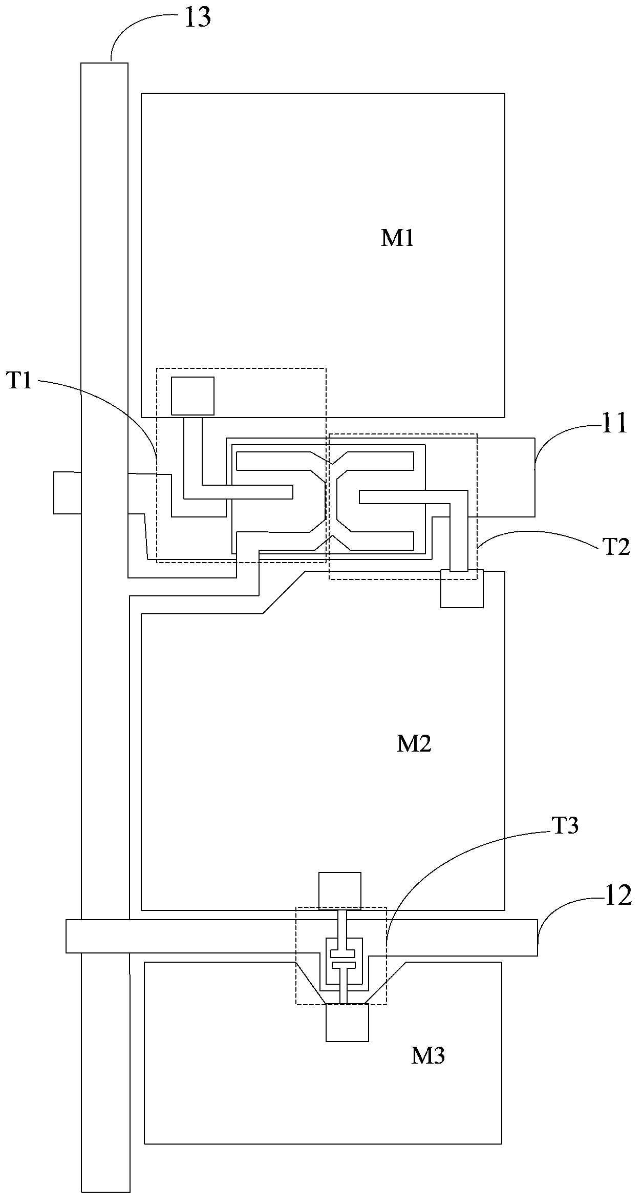
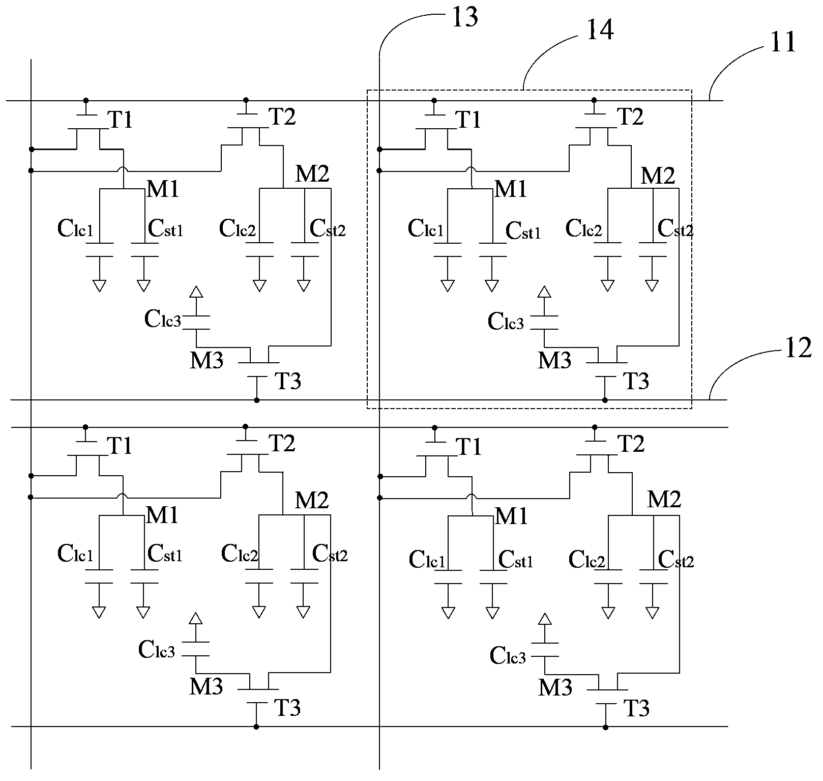
[0024] refer to figure 1, In an embodiment of the array substrate of the present invention, the array substrate includes a plurality of first scan lines 11 , a plurality of second scan lines 12 , a plurality of data lines 13 and a plurality of pixel units...


PUM


Abstract

The invention discloses an array substrate and a liquid crystal display panel. In the array substrate, each pixel unit comprises a first pixel electrode, a second pixel electrode and a third pixel electrode. Each third pixel electrode is connected with one second pixel electrode through a third switch. Each third switch is connected under a 2D display mode so that each second pixel electrode can be electrically connected with one third pixel electrode, each first pixel electrode, the corresponding second pixel electrode and the corresponding third pixel electrode can be respectively in the state that a corresponding image of a 2D picture is displayed and the voltage of each second pixel electrode can be changed through the voltage of the corresponding third pixel electrode. Under a 3D display mode, each second pixel electrode is not communicated with the corresponding third pixel electrode, so that each third pixel electrode is in the state that a corresponding image of a black picture is displayed. According to the mode, the aperture ratio under the 2D display mode is improved, color distortion under a large viewing angle is reduced, and meanwhile, double-eye signal crosstalk under the 3D display mode is reduced.

Description

technical field [0001] The invention relates to the field of display technology, in particular to an array substrate and a liquid crystal display panel. Background technique [0002] Compared with traditional displays, liquid crystal displays have the advantages of flicker-free images, saturated colors, and small size. They mainly use the physical structure and optical properties of liquid crystal molecules to achieve display. However, under different viewing angles, the orientation of the liquid crystal molecules is not the same, so that the effective refractive index of the liquid crystal molecules is also different, which will cause changes in the transmitted light intensity. The colors displayed in the direction of viewing angle and the direction of normal viewing angle are inconsistent, and chromatic aberration occurs, so color distortion will be observed at large viewing angles. [0003] In addition, with the development of liquid crystal display technology, most liqu...

Claims


Application Information

Patent Timeline
Patent Type & Authority Applications(China)
IPC IPC(8): G02F1/1362G02F1/1368
CPCG02F1/13624G09G3/003G09G3/3648G09G2320/0209G02F1/134345H04N13/356G02F1/1368
Inventor 姚晓慧许哲豪党娟宁
Owner TCL CHINA STAR OPTOELECTRONICS TECH CO LTD
Learn More