
Single-channel expanded beam connector

a single-channel, expanded beam technology, applied in optics, instruments, optical light guides, etc., can solve the problems of affecting the optical transmission, and the physical contact between the fiber and the light path of the mating connector is problematic, so as to reduce the back reflection, reduce the overall dimension, and reduce the form factor

Active Publication Date: 2010-08-17
TYCO ELECTRONICS LOGISTICS AG (CH)
View PDF7 Cites 116 Cited by
  • Summary
  • Abstract
  • Description
  • Claims
  • Application Information

AI Technical Summary

Benefits of technology

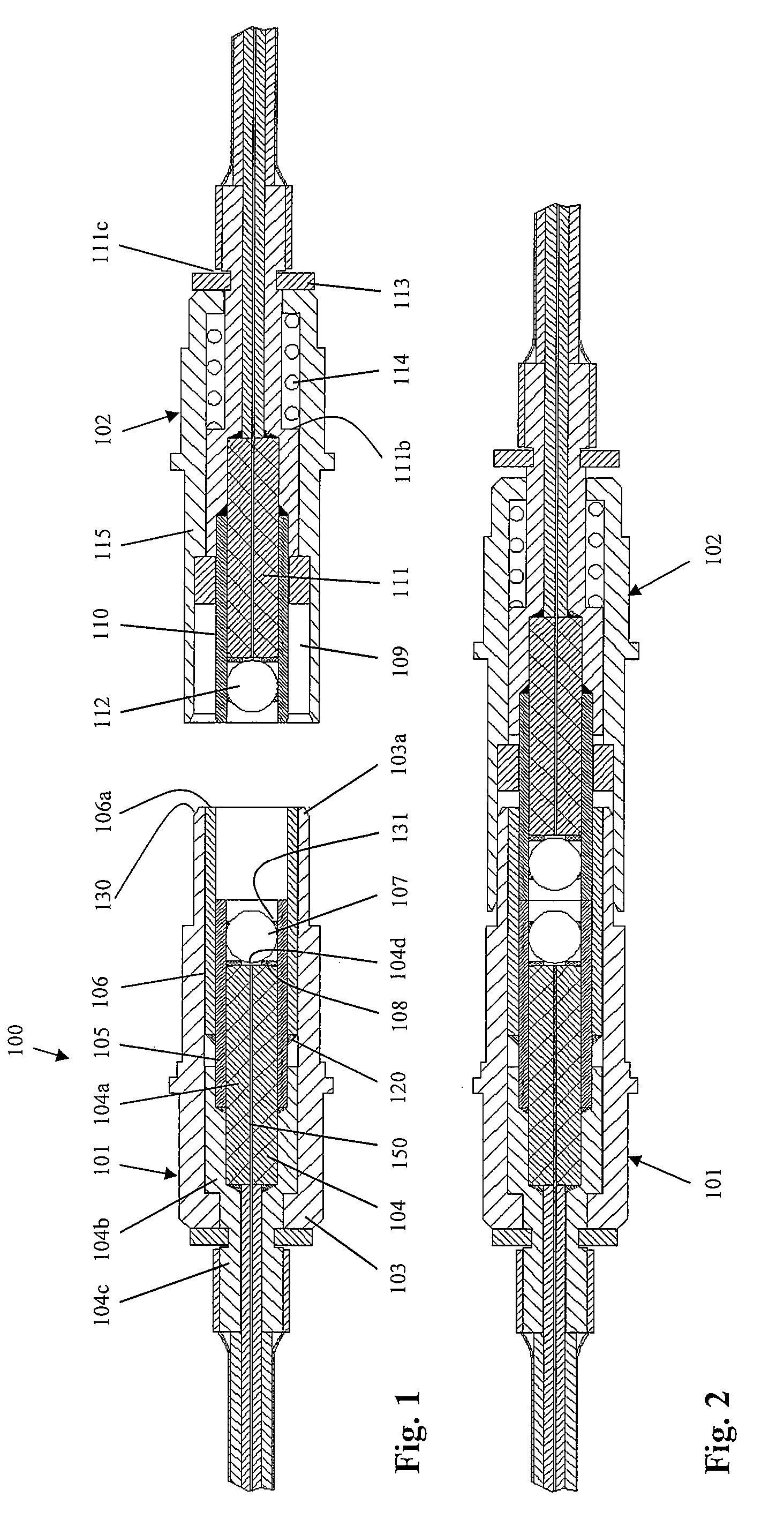
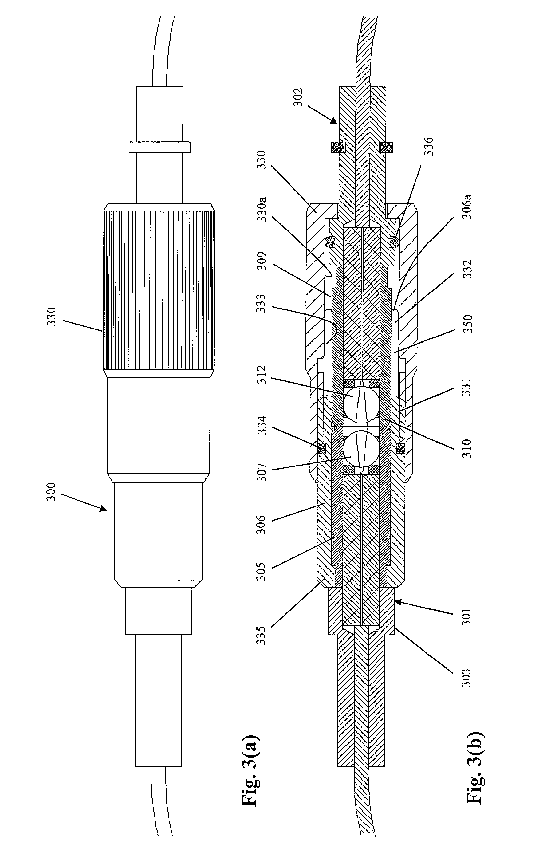
[0008]The present invention provides a single-channel expanded beam connector that exploits the outside dimensions of various optical components to hold and align them in a discrete optical subassembly. Specifically, the present invention recognizes that producing optical components, for example, a ferrule and a lens, with the same outside diameter is readily achievable. These components can then be held in alignment in a compact, cylindrical sleeve to form the subassembly. If the components are designed with good concentricity, it follows that the optical alignment among the components in the cylindrical sleeve is also achieved. The present invention optically couples different optical devices by conveniently aligning the subassembly of each device in a second, common sleeve. Thus, the present invention offers a single-channel connector having a small form factor and a low insertion loss (good optical alignment).
[0010]The connector design of the present invention offers a number of important advantages over conventional connectors. For example, by using discrete cables and channels, the connector system allows for branching out of cables in different directions. Furthermore, because the ferrule and lens are contained in a compact, precision sleeve, the connector has a relatively small form factor, especially compared to prior art expanded beam connectors. For example, in one embodiment, a mated pair of the connectors of the present invention has a smaller overall dimension than a mated pair of standard FC connectors. Still another advantage is that the connector system of the present invention does not need an adapter as required by the FC connector. FC connectors are typically mated via an alignment sleeve contained within the adaptor. For the present invention the sleeve is integral to the connector system. Nor does the present invention make use of alignment pins which are typically used for prior art expanded beam systems. The design is also flexible with respect to the optical interface. For example, it allows the ferrule assembly to make use of the glass block concept as disclosed in U.S. Patent Publication No. 20080050073 (hereby incorporated by reference), or the ferrule can have a slant polish in order to reduce the back reflection of a single mode optical signal at the fiber / air interface or be a combination of the glass block concept and a slant polish. Further, similar to the prior art PROBEAM expanded beam system, the single mode version can have physical contact between the fiber and the lens. Still other uses and advantages of the present invention will be apparent to one of skill in the art in light of this disclosure.

Problems solved by technology

Such connectors are used traditionally in high vibration and / or dirty environments, where “physical contact” between the fiber and the light path of mating connector is problematic.
Specifically, in dirty environments, particulates may become trapped between connectors during mating.
Such debris has a profoundly detrimental effect on the optical transmission since the particles are relatively large compared to the optical path (e.g., 10 microns diameter in single mode) and are therefore likely to block at least a portion of the optical transmission.
Furthermore, in high-vibration environments, optical connectors having ferrules in physical contact tend to experience scratching at their interface.
This scratching diminishes the finish of the fiber end face, thereby increasing reflective loss and scattering.
Radial offsets of only a few microns can affect insertion losses significantly.
Applicant has identified that this configuration limits the ability of the cables of individual channels to branch out independently and thus makes such connectors unsuitable for backplane and similar applications.

Method used


Image

  • Single-channel expanded beam connector
  • Single-channel expanded beam connector
  • Single-channel expanded beam connector

Examples


Embodiment Construction

[0018]The present invention provides for an expanded beam connector system to ensure reliable and repeatable optical coupling between the fiber of a connector and the optical pathway(s) of a mating optical structure. The term “optical pathway,” as used herein, refers to any medium for conducting optical signals including the following: a fiber or waveguide; a silica-based or polymeric structure in a substrate; or a silica-based or polymeric optical component. The term “mating component” refers to an optical package that contains or comprises the optical pathway. For example, a mating component may be another connector, herein a “mating connector” or it may be an optical device in which the optical pathway is an integral component. Examples of optical devices include passive devices, such as, add / drop filters, arrayed waveguide gratings (AWGs), splitters / couplers, and attenuators, and active devices, such as, optical amplifiers, transmitters, receivers and transceivers.

[0019]Referrin...


PUM


Abstract

A single-channel, expanded beam connector having a front and rear orientation and comprising: (a) a housing; (b) an outer sleeve at least partially contained by the housing; (c) a first inner sleeve disposed at least partially in the outer sleeve; (d) a ferrule disposed at least partially in the first inner sleeve; (e) a lens disposed at least partially in the first inner sleeve in front of the ferrule, wherein the lens and the ferrule have about the same outside first diameter which is just slightly less than that of the inside diameter of the first inner sleeve such that the ferrule and the lens are held in optical alignment in the first inner sleeve, and wherein the distal end of the outer sleeve extends beyond the inner sleeve to receive a second inner sleeve of a mating structure, the first and second inner sleeves having the same diameter which is just slightly less than the inside diameter of the outer sleeve such that the first and inner sleeves are aligned within the outer sleeve.

Description

FIELD OF INVENTION[0001]The present invention relates generally to an expanded beam optical connector, and, more specifically, to a single-channel expanded beam optical connector.BACKGROUND OF INVENTION[0002]Optical fiber connectors are a critical part of essentially all optical fiber communication systems. For instance, such connectors are used to join segments of fiber into longer lengths, to connect fiber to active devices, such as radiation sources, detectors and repeaters, and to connect fiber to passive devices, such as switches, multiplexers, and attenuators. The principal function of an optical fiber connector is to hold the fiber end such that the fiber's core is axially aligned with an optical pathway of the mating structure. This way, light from the fiber is optically coupled to the optical pathway.[0003]Of particular interest herein are “expanded beam” optical connectors. Such connectors are used traditionally in high vibration and / or dirty environments, where “physical ...

Claims


Application Information

Patent Timeline
Patent Type & Authority Patents(United States)
IPC IPC(8): G02B6/38
CPCG02B6/32G02B6/3874
Inventor GRINDERSLEV, SOREN
Owner TYCO ELECTRONICS LOGISTICS AG (CH)
Learn More