Control device and control method to exhaust purification device

a technology of control device and control method, which is applied in the direction of machines/engines, mechanical equipment, separation processes, etc., can solve the problems of reducing the fuel supply pressure and the exhaust purification rate may drop, so as to curb the deterioration of the degree of atomization of an additive and the exhaust purification ra

Inactive Publication Date: 2010-08-17
TOYOTA JIDOSHA KK +1
View PDF18 Cites 5 Cited by
  • Summary
  • Abstract
  • Description
  • Claims
  • Application Information

AI Technical Summary

Benefits of technology

[0008]The invention provides a control device and a control method of an exhaust purification device that is capable of curbing the decline of the exhaust purification rate by curbing the deterioration of the degree of atomization of an additive.
[0010]This will curb the drop of the supply pressure of the additive caused by simultaneous supply of the additive from the plurality of addition valves. As a result, the above-described construction, in comparison with a construction in which the additive is supplied simultaneously from all of addition valves, is able to maintain a higher supply pressure for the additive relatively, and hence is able to curb the deterioration of the degree of atomization of the additive and therefore curb the decline of the exhaust purification rate.
[0011]In a second aspect of the invention the plurality of addition valves are two addition valves that are provided separately in two systems of exhaust passageways, and in which, as for the two addition valves, the addition period of one addition valve is set so as not to overlap with the addition period of the other addition valve. Therefore, the addition periods of the two addition valves shift from each other. Hence, the above-described construction is able to curb the drop of the supply pressure of the additive which is caused when the additive is supplied via the addition valves.
[0013]Therefore, in the third aspect of the invention, the addition period of at least one addition valve is set so as to be different from the addition period of another addition valve. Hence, although the exhaust purification device has the above-described construction, the third aspect is able to curb the deterioration of the degree of atomization of the additive and therefore curb the decline of the exhaust purification rate.
[0015]According to this construction, when the supply of the additive via the addition valves begins, the pressure of the additive in the common portion of the supply passageway, which connects the pump and the addition valves, is greater than or equal to a predetermined magnitude. Therefore, the fourth aspect is able to curb the deterioration of the degree of atomization of the additive and therefore curb the decline of the exhaust purification rate.

Problems solved by technology

This greatly reduces the fuel supplying pressure.
As a result, the degree of atomization of fuel in exhaust passageways 2R, 2L may deteriorate, so that the fuel may not be sufficiently supplied to the surface of the catalyst, and therefore the exhaust purification rate may drop.

Method used


Image

  • Control device and control method to exhaust purification device
  • Control device and control method to exhaust purification device
  • Control device and control method to exhaust purification device

Examples


first embodiment

[0029]the invention is shown as a control device of an exhaust purification device disposed on a V-type 6-cylinder diesel engine, as shown in detail with reference to FIGS. 1 to 5E.

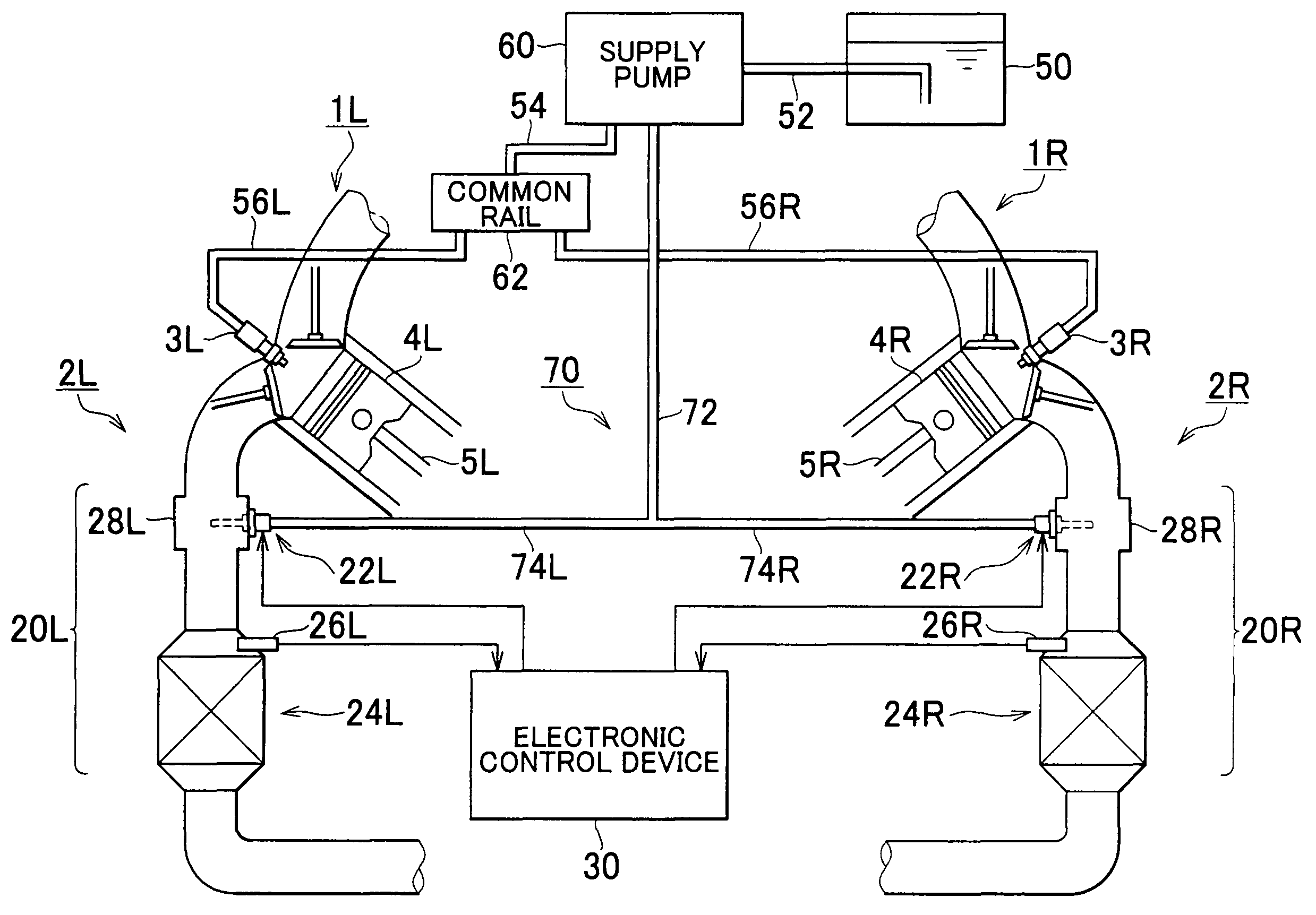
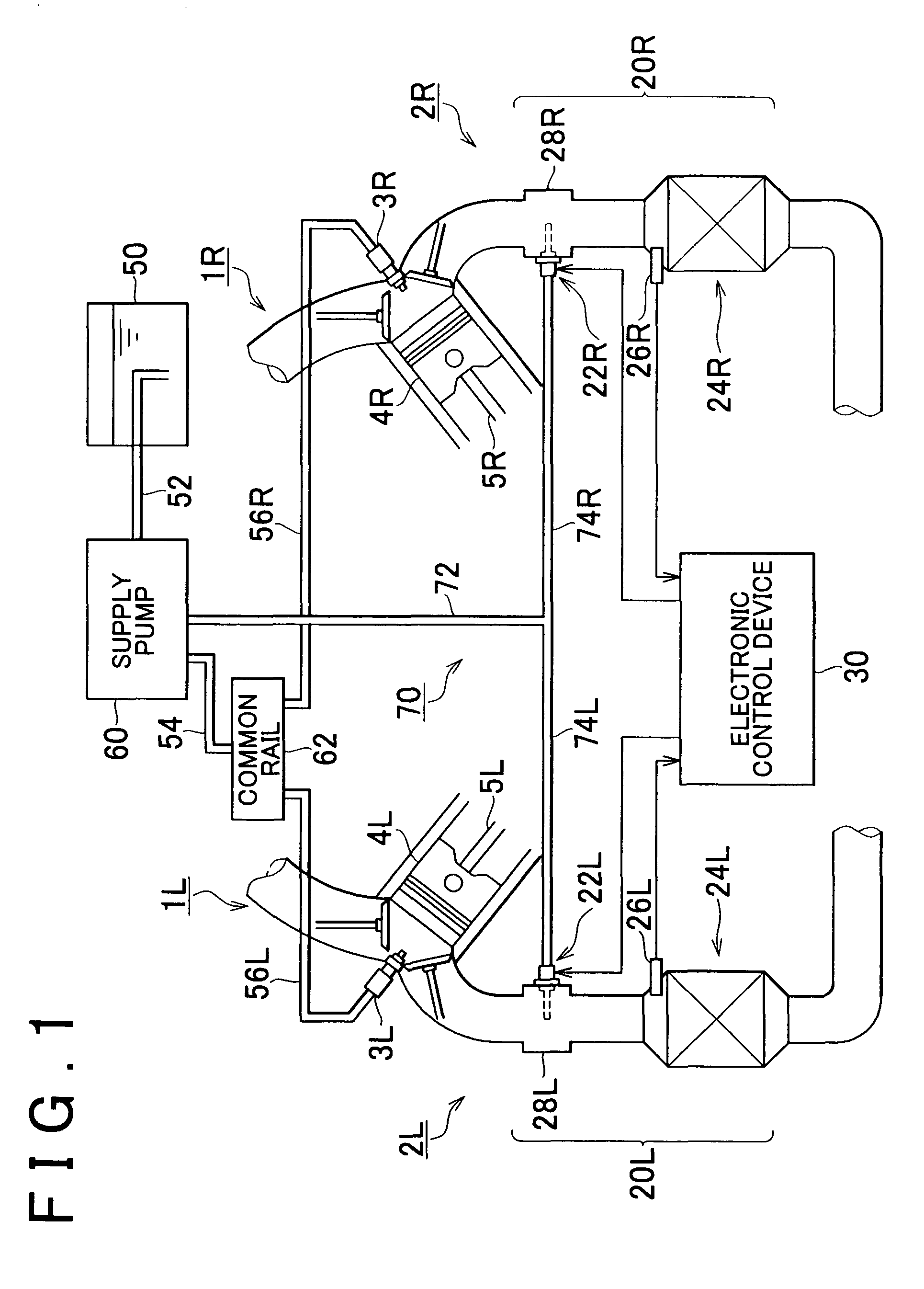
[0030]As shown in FIG. 1, the right and left banks of a V-type 6-cylinder engine are each provided with three cylinders. To simplify the description herein, only the foremost cylinders, among the cylinders of the right and left banks, are shown in FIG. 1.

[0031]The engine has intake passageways 1R, 1L for supplying intake air into the cylinders, and exhaust passageways 2R, 2L for discharging exhaust gas produced by combustion in each cylinder. Intake manifolds are disposed respectively on the right and left banks as portions for connection of the intake passageways 1R, 1L to the cylinders. Intake air supplied through the intake passageways 1R, 1L is introduced into the cylinders through the intake manifolds.

[0032]Each cylinder is provided with a fuel injection valve 3R, 3L. As fuel injected from the fuel i...


PUM


Abstract

A control device of an exhaust purification device is provided with a plurality of addition valves that supply an additive pressure-fed from a pump, to exhaust purification catalysts separately from each other. As for addition valves constituting the plurality of addition valves the addition period of at least one addition valve is set so as to be different from the addition period of another addition valve.

Description

INCORPORATION BY REFERENCE[0001]The disclosure of Japanese Patent Application No. 2005-209127 filed on Jul. 19, 2005 including the specification, drawings and abstract is incorporated herein by reference in its entirety.BACKGROUND OF THE INVENTION[0002]1. Field of the Invention[0003]The invention relates to a control device and a control method of an exhaust purification device.[0004]2. Description of the Related Art[0005]Some diesel engines and the like have, in their exhaust passageways, an exhaust purification device that includes a catalyst for purifying the exhaust gas. Examples of such catalysts include a NOx storage-reduction catalyst, which remove NOx (oxides of nitrogen) by the reduction thereof, and the like. The NOx storage-reduction catalyst stores NOx from the exhaust gas in an oxidizing atmosphere, and releases stored NOx and reduces it to nitrogen in a reducing atmosphere. Specifically, when a predetermined condition regarding the engine operation state or the like is...

Claims


Application Information

Patent Timeline
Patent Type & Authority Patents(United States)
IPC IPC(8): F01N3/00B01D53/94F01N3/02F01N3/023F01N3/025F01N3/029F01N3/08F01N3/24F01N3/36F01N13/04
CPCF01N3/0253F01N3/035F01N3/0842F01N13/011F01N3/0885F01N3/0871F01N2610/03
Inventor SUZUKI, HISANOBUNAMIKI, TADACHIKAKAWAI, KENJI
Owner TOYOTA JIDOSHA KK
Why Eureka
Try Eureka