
Liquid droplet jetting apparatus

a technology of liquid droplet and jetting apparatus, which is applied in the direction of printing, other printing apparatus, etc., can solve the problems of reducing the accuracy of landing position, affecting the flight trajectory of satellite liquid droplets, and affecting the accuracy of landing positions, so as to achieve superior liquid repellent properties and prevent flying. assured

Active Publication Date: 2010-03-30
BROTHER KOGYO KK
View PDF15 Cites 0 Cited by
  • Summary
  • Abstract
  • Description
  • Claims
  • Application Information

AI Technical Summary

Benefits of technology

This solution ensures accurate landing of satellite droplets by shielding them from environmental influences and maintaining the fluidity of main droplets for easy reuse, enhancing printing quality and reducing component count and size.

Problems solved by technology

Since a volume of a satellite liquid droplet is very small and a satellite liquid droplet is very light in weight, while traveling from the nozzle up to the recording medium, the flying trajectory of the satellite liquid droplet is susceptible to change due to dust which is dispersed, and a flow of a gas (air) in a space in a surrounding area.
Therefore, there is a problem of a decline in accuracy of a landing position at which the satellite liquid droplet is landed.

Method used


Image

  • Liquid droplet jetting apparatus
  • Liquid droplet jetting apparatus
  • Liquid droplet jetting apparatus

Examples


first modified embodiment

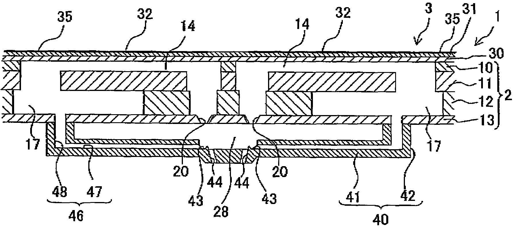
[0095]In the embodiment described above, the projection 45 is formed between the main liquid droplet trapping section 43 and the through holes 44, with an object of preventing the main liquid droplet trapped by the main liquid droplet trapping section 43, from flowing into the through holes 44 (for example, refer to FIG. 5). However, as shown in FIG. 11 and FIG. 12, instead of the projection 45, a highly liquid repellent area 50 having a liquid repellent property superior to a liquid repellent property of the main liquid droplet trapping section 43 may be formed between the through holes 44 and the main liquid droplet trapping section 43, on an upper surface of a bottom wall 41A of a cover member 40A. Even in this structure, since the main liquid droplet landed on the main liquid droplet trapping section 43 cannot cross over the highly liquid repellent area 50, and move into the through holes 44, the main liquid droplet is prevented assuredly from flowing into the through hole 44.

second modified embodiment

[0096]Furthermore, in the first modified embodiment, the highly liquid repellent area may be formed such that an area of the highly liquid repellent area is decreased progressively toward the main liquid droplet trapping section, or as shown in FIG. 13, a portion of a highly liquid repellent area 50B toward the main liquid droplet trapping section 43 may be formed to have a zigzag shape having a sharp angular portion, and the area of the highly liquid repellent area 50B may be decreased progressively toward the main liquid droplet trapping section 43.

third modified embodiment

[0097]The liquid repellent property of the highly liquid repellent area may be low toward the area of the main liquid droplet trapping section. As shown in FIG. 14, a plurality of holes 51 may be formed in a portion of a highly liquid repellent area 50C, on a side of the main liquid droplet trapping section 43, and the holes 51 may be arranged more densely, progressively toward the main liquid droplet trapping section 43, such that the area of the highly liquid repellent area 50C is decreased progressively toward the main liquid droplet trapping section 43.


PUM


Abstract

An ink-jet printer includes an ink-jet head which includes a nozzle, a main liquid droplet trapping section 30 which traps only a main liquid droplet, and a cover member which surrounds a space in which a satellite liquid droplet which is jetted from a nozzle at the same time when the main liquid droplet is jetted, flies. It is possible to suppress a decline in an accuracy of a landing position of the satellite liquid droplet, caused due to a change in a trajectory of flying of the satellite liquid droplet due to an effect of a flow of air in the space. Accordingly, it is possible to provide a liquid droplet jetting apparatus which is capable of controlling accurately the landing position of a very small satellite liquid droplet.

Description

CROSS REFERENCE TO RELATED APPLICATION[0001]The present application claims priority from Japanese Patent Application No. 2005-282733, filed on Sep. 28, 2005, the disclosure of which is incorporated herein by reference in its entirely.BACKGROUND OF THE INVENTION[0002]1. Field of the Invention[0003]The present invention relates to a liquid droplet jetting apparatus which jets liquid droplets.[0004]2. Description of the Related Art[0005]In recent years, in a field of liquid droplet jetting apparatuses which jet liquid droplets, a technology for jetting a very small liquid droplet has been required. For example, in an ink-jet head which jets ink onto a recording paper, for recording an image of a high quality, a technology for jetting a very small droplet has been required. Moreover, a technology to jet an extremely small liquid droplet is required also in cases such as forming a fine wiring pattern on a substrate by jetting an electroconductive paste, forming a high definition display ...

Claims


Application Information

Patent Timeline
Patent Type & Authority Patents(United States)
IPC IPC(8): B41J29/38
CPCB41J2/14233B41J2/1433B41J2/185B41J2002/14266B41J2002/14475
Inventor SUGAHARA, HIROTO
Owner BROTHER KOGYO KK
Learn More