
Methods for operating a selective stiffening catheter

a selective stiffening and catheter technology, applied in the field of medical devices, can solve the problems of inability to generate the force required to advance the guidewire through the lesion, inhibit the advancement of the guidewire, and no catheter-based standard accepted practice for cto treatmen

Inactive Publication Date: 2010-08-10
SYN VARIFLEX LLC
View PDF8 Cites 33 Cited by
  • Summary
  • Abstract
  • Description
  • Claims
  • Application Information

AI Technical Summary

Benefits of technology

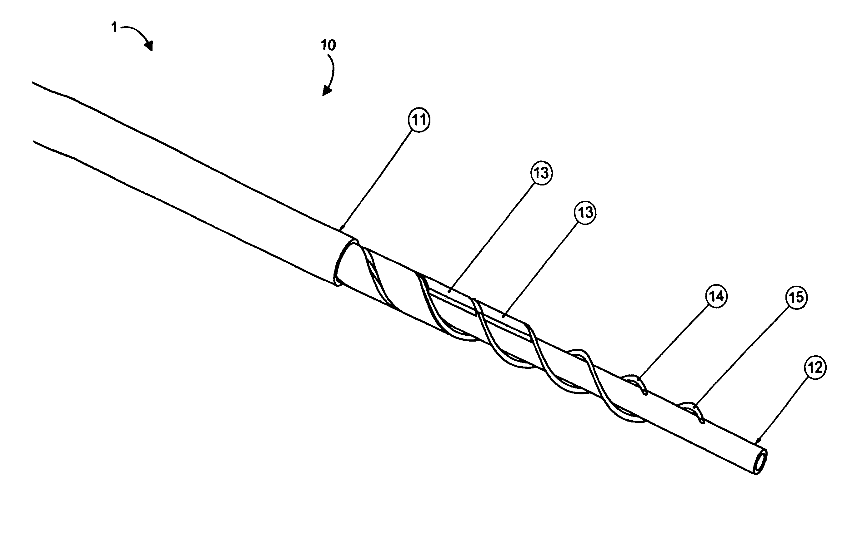
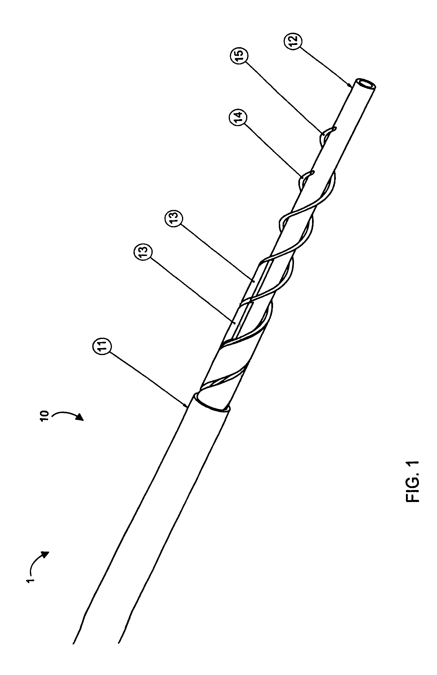
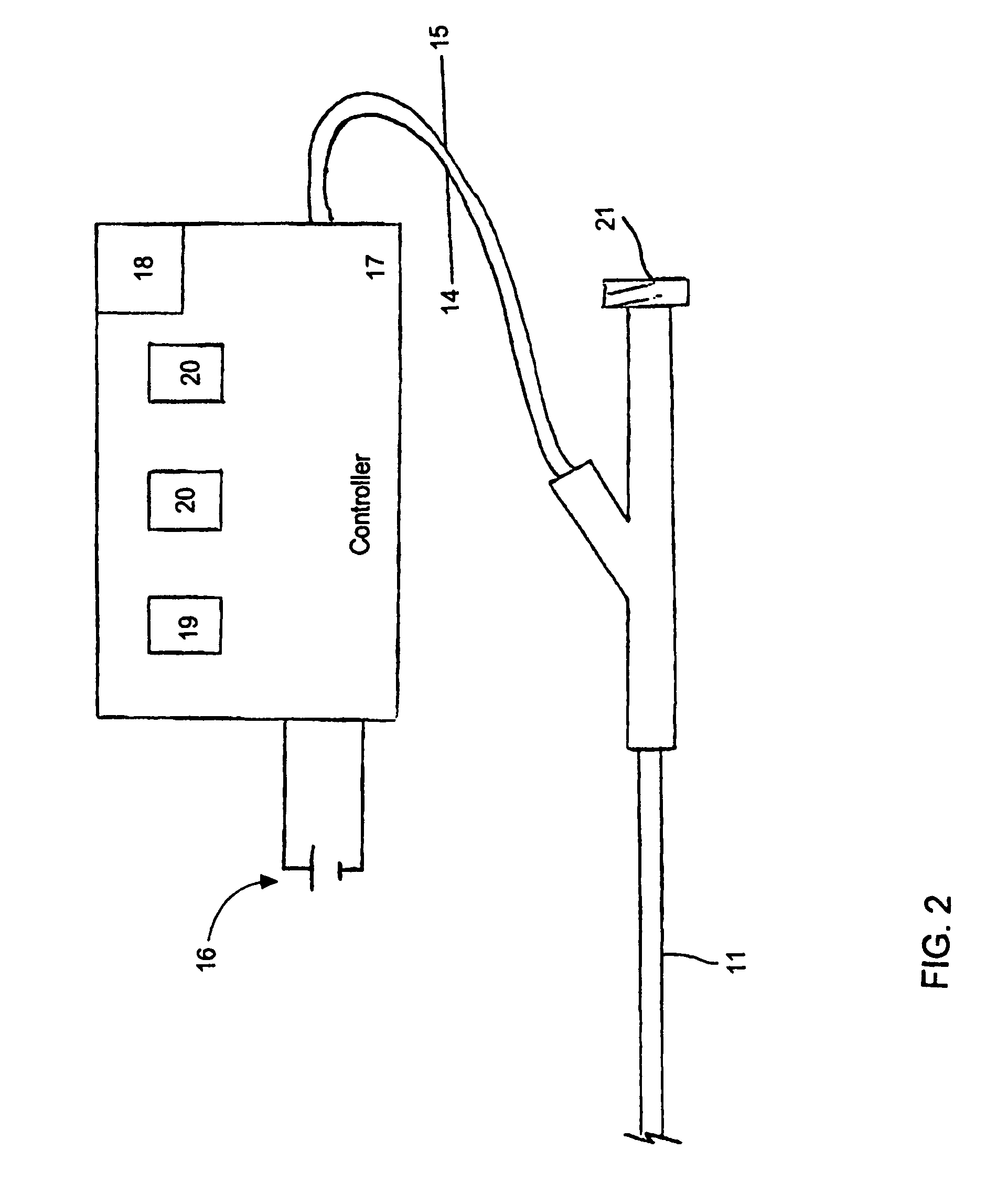
"The present invention provides a controllable stiffness catheter that can be used to deliver tools to treatment sites in the body, particularly for the cross-crossing of arterial blockages. The catheter has a stiffness that can be controlled by the physician during use, allowing for flexibility in conforming to the anatomy of the body and maintaining a stiff state at the treatment site. The catheter can be made stiffer or softer as needed, and can be designed to cycle between stiff and soft states repeatedly. The stiffness of the catheter can be controlled through the use of a stiffness device and a power controller, which selectively supplies power to the stiffness device. The catheter can be designed to maintain its stiffness when the stiffness device is not in use, and can be designed to change its stiffness when the stiffness device is activated. The catheter can be used in the treatment of difficult-to-cross lesions and can provide better support and control during the process."

Problems solved by technology

In the case of complete or nearly complete blockage, the force required to advance the guidewire through the lesion can be difficult for the physician to generate by pushing on the flexible guidewire from the arterial access site.
Further, this access site may be far from the treatment site, such as in the case of coronary arterial treatment where access to the coronary arteries is gained though the femoral artery.
The same flexibility that helped gain access to the treatment site now inhibits the advancement of the guidewire.
These provide an improvement over balloon catheters but are also limited by how flexible they must be to reach the treatment site.
And, there is no catheter-based standard accepted practice for CTO treatment.
Specialty guidewires are available to aid the physician in this effort but they, too, are limited in their utility by the constraints of flexibility and compliance.
It is noted that attempting to cross CTOs is a tedious practice with current equipment and is met with limited success.
Common problems encountered in this procedure are difficulty in precisely locating the aberrant tissue, and complications related to the ablation of the tissue.
Locating the area of tissue causing the arrhythmia often involves several hours of electrically “mapping” the inner surface of the heart using a variety of mapping catheters, and once the aberrant tissue is located, it is often difficult to position the catheter and the associated electrode or probe so that it is in contact with the desired tissue.
The application of either RF energy or ultra-low temperature freezing to the inside of the heart chamber also carries several risks and difficulties.
It is very difficult to determine how much of the catheter electrode or cryogenic probe surface is in contact with the tissue since catheter electrodes and probes are cylindrical and the heart tissue cannot be visualized clearly with existing fluoroscopic technology.
Further, because of the cylindrical shape, some of the exposed electrode or probe area will almost always be in contact with blood circulating in the heart, giving rise to a risk of clot formation.
Clot formation is almost always associated with RF energy or cryogenic delivery inside the heart because it is difficult to prevent the blood from being exposed to the electrode or probe surface.
Some of the RF current flows through the blood between the electrode and the heart tissue and this blood is coagulated, or frozen when a cryogenic probe is used, possibly resulting in clot formation.
When RF energy is applied, the temperature of the electrode is typically monitored so as to not exceed a preset level, but temperatures necessary to achieve tissue ablation almost always result in blood coagulum forming on the electrode.
Overheating or overcooling of tissue is also a major complication, because the temperature monitoring only gives the temperature of the electrode or probe, which is, respectively, being cooled or warmed on the outside by blood flow.
The actual temperature of the tissue being ablated by the electrode or probe is usually considerably higher or lower than the electrode or probe temperature, and this can result in overheating, or even charring, of the tissue in the case of an RF electrode, or freezing of too much tissue by a cryogenic probe.
Overheated or charred tissue can act as a locus for thrombus and clot formation, and over freezing can destroy more tissue than necessary.
It is also very difficult to achieve ablation of tissue deep within the heart wall.
When used from an endocardial approach, the limitations of all energy-based ablation technologies to date are the difficulty in achieving continuous transmural lesions and minimizing unnecessary damage to endocardial tissue.
However, this technology creates rather wide (greater than 5 mm) lesions that could lead to stenosis (narrowing) of the pulmonary veins.
Additionally, there is no feedback to determine when full transmural ablation has been achieved.
Consequently, there is no energy delivered at the backplate / tissue interface intended to ablate tissue.
It is important to note that all endocardial ablation devices that attempt to ablate tissue through the full thickness of the cardiac wall have a risk associated with damaging structures within or on the outer surface of the cardiac wall.
As an example, if a catheter is delivering energy from the inside of the atrium to the outside, and a coronary artery, the esophagus, or other critical structure is in contact with the atrial wall, the structure can be damaged by the transfer of energy from within the heart to the structure.
The coronary arteries, esophagus, aorta, pulmonary veins, and pulmonary artery are all structures that are in contact with the outer wall of the atrium, and could be damaged by energy transmitted through the atrial wall.

Method used


Image

  • Methods for operating a selective stiffening catheter
  • Methods for operating a selective stiffening catheter
  • Methods for operating a selective stiffening catheter

Examples


Embodiment Construction

[0076]Aspects of the invention are disclosed in the following description and related drawings directed to specific embodiments of the invention. Alternate embodiments may be devised without departing from the spirit or the scope of the invention. Additionally, well-known elements of exemplary embodiments of the invention will not be described in detail or will be omitted so as not to obscure the relevant details of the invention.

[0077]While the specification concludes with claims defining the features of the invention that are regarded as novel, it is believed that the invention will be better understood from a consideration of the following description in conjunction with the drawing figures, in which like reference numerals are carried forward.

[0078]Before the present invention is disclosed and described, it is to be understood that the terminology used herein is for the purpose of describing particular embodiments only and is not intended to be limiting. It must be noted that, a...


PUM


Abstract

A method for delivering RF energy to living tissue includes the steps of extending a guidewire to a tissue treatment site in a body. A controllable stiffness catheter is provided with a stiffness device and a temperature-changing device. The stiffness device is in a stiff state below a given temperature and in a soft state above the given temperature. While supplying power to the temperature-changing device, the catheter is threaded along the guidewire up to the treatment site in the flexible state of the catheter. Power is removed from the temperature-changing device to change stiffness of the stiffness device to the stiff state without straightening the catheter. The RF energy supply device is physically contacted with the treatment site and RF energy is delivered to the treatment site from the RF energy supply device.

Description

CROSS-REFERENCE TO RELATED APPLICATION[0001]This application claims the priority, under 35 U.S.C. §119, of U.S. Provisional Patent Application No. 60 / 612,684 filed Sep. 24, 2004, and is a continuation in part of copending U.S. patent application Ser. No. 11 / 233,993, filed Sep. 23, 2005, and entitled “Catheter with Controllable Stiffness and Method for Operating a Selective Stiffening Catheter,” the entire disclosures of which are hereby incorporated herein by reference in their entireties.STATEMENT REGARDING FEDERALLY SPONSORED RESEARCH OR DEVELOPMENT[0002]n / aFIELD OF THE INVENTION[0003]The invention lies in the field of medical devices, namely, catheters. In particular, the invention relates to catheters that can change stiffness characteristics in use and their uses.BACKGROUND OF THE INVENTION[0004]To gain access to treatment sites in the body, catheters must be flexible enough to conform to and follow natural anatomical pathways as they are advanced. These pathways can be quite t...

Claims


Application Information

Patent Timeline
Patent Type & Authority Patents(United States)
IPC IPC(8): A61M25/00
CPCA61B18/1492A61F2/01A61M25/005A61M25/0054A61M25/01A61B18/00A61B2018/00351A61M25/0053A61M25/104A61M2025/0063A61M2025/0064A61F2230/005A61F2/0105A61B2018/00357A61B2018/00577
Inventor SMITH, KEVIN W.PALMER, MATTHEW A.MCBRAYER, SEANBALES, THOMAS O.DEVILLE, DEREK DEEABELLEIRA, JOE
Owner SYN VARIFLEX LLC
Learn More