
Methods for operating a selective stiffening catheter

Inactive Publication Date: 2006-09-21
SYN VARIFLEX LLC
View PDF8 Cites 84 Cited by
  • Summary
  • Abstract
  • Description
  • Claims
  • Application Information

AI Technical Summary

Benefits of technology

[0011] The catheter of the present invention provides a platform on which physicians can deliver tools to treatment sites to aid in the crossing of arterial blockages, especially, CTOs. In the stiff state, these tools can be used and the force applied by the tools on the treatment site can be enhanced and increased based upon the stiffness properties of the catheter.
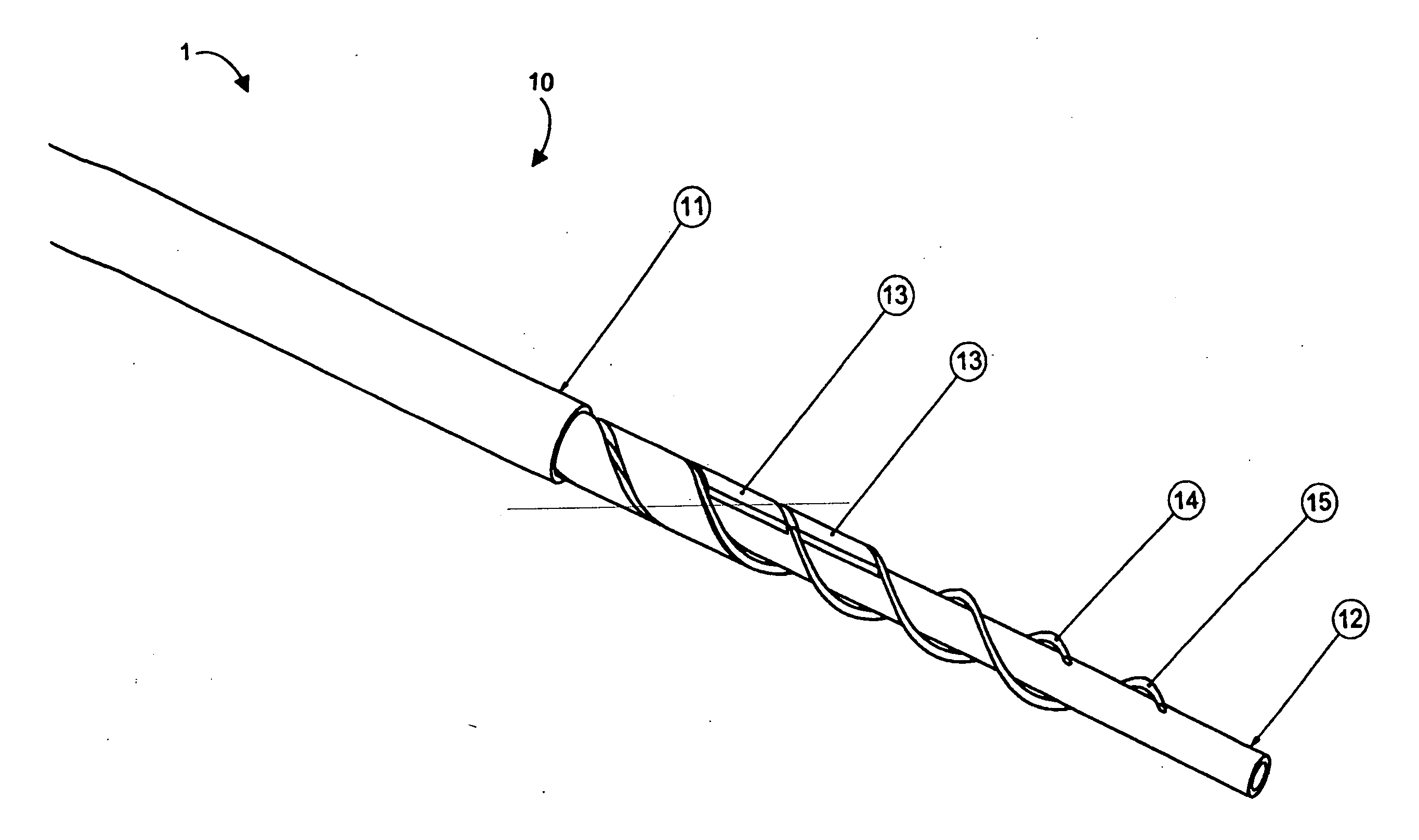
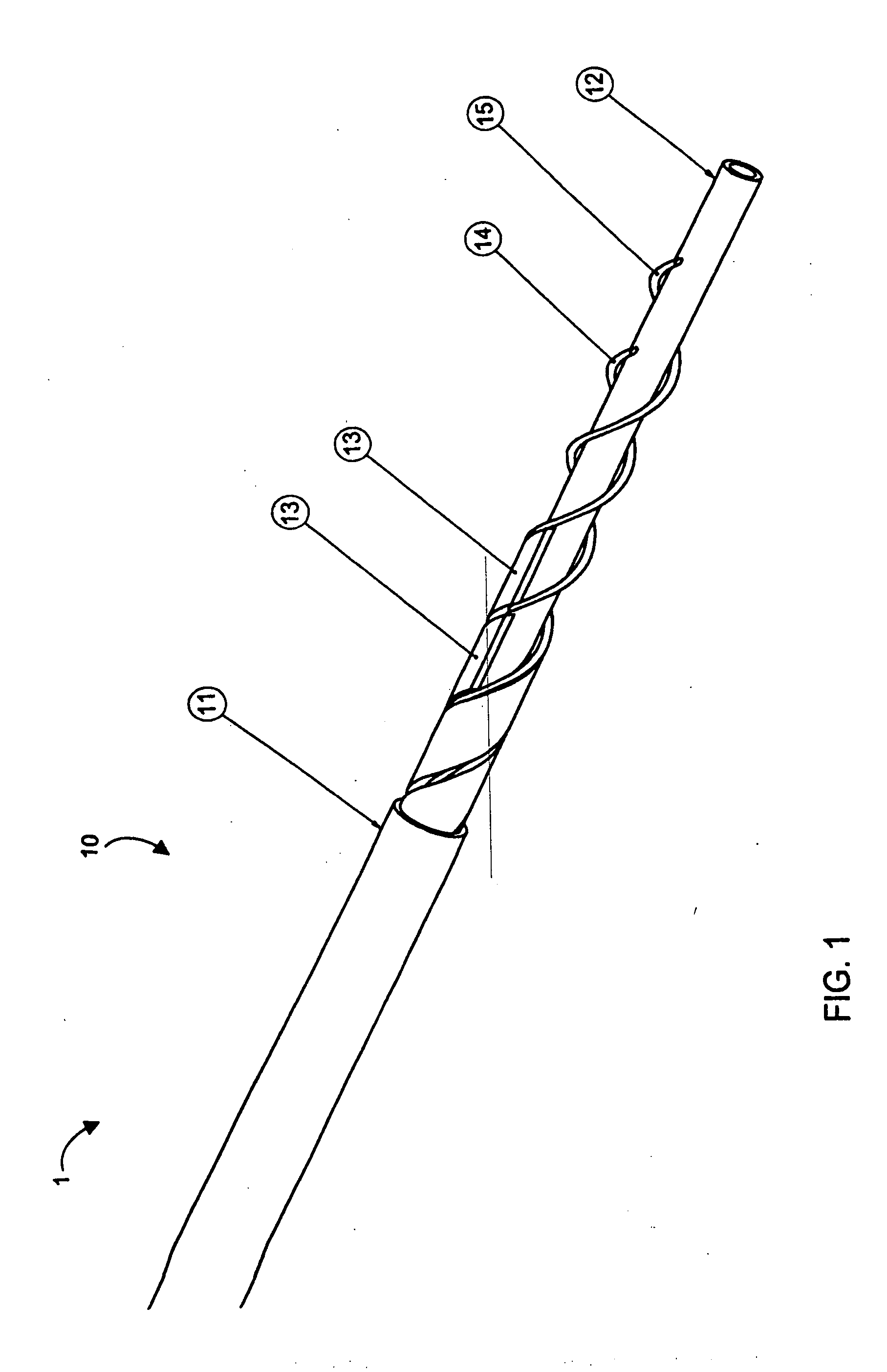
[0013] The catheter is delivered to the treatment site in the flexible state, in which, it will track over the guidewire and conform to the anatomical pathway, e.g., the vasculature. Once in-place, the catheter can be made to become stiff (either in whole or in part) without straightening and, thereby, maintain its conformance to the vasculature. In such a state, the catheter provides a stiff conduit to deliver tools to the treatment site without compromising the natural anatomy. This stiffness provides the support necessary to efficiently advance the guide or crossing wires without loss of motion and efficiently transmit thrust loads to the tools.
[0014] In the case of a guidewire as described above, the guidewire will, with use of the catheter according to the invention, not flex away from the treatment site when pushed and provides great increases in feel, control, and thrust. Such characteristics aid in the successful crossing of difficult-to-cross lesions and provide an opportunity to cross CTOs.
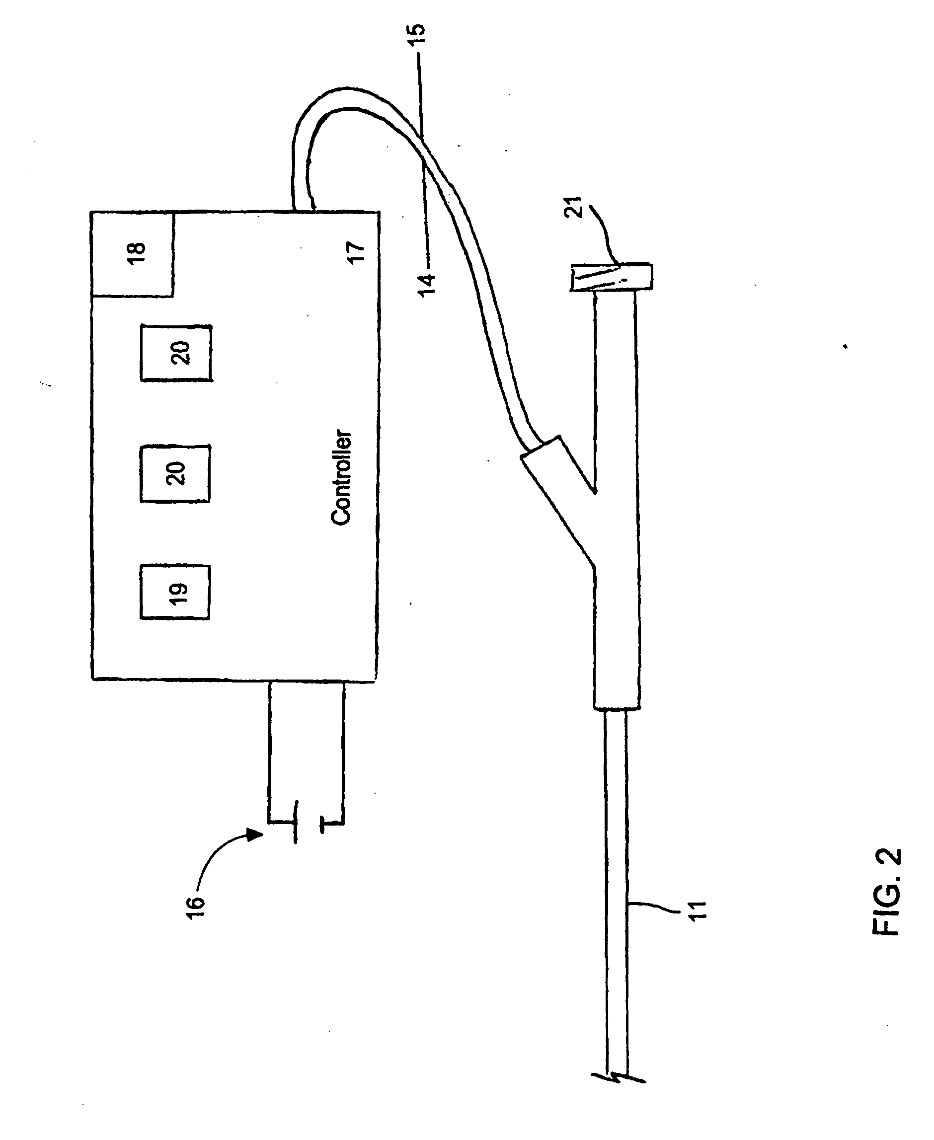
[0030] In accordance with yet an added feature of the invention, the controller selectively applies a voltage to the first and second electrical conductors to cause current to flow through the circuit and resistively heat the at least one carbon fiber tow and to remove current flowing through the circuit and cool the at least one carbon fiber tow. The heated carbon fiber tow melts and softens the binder to allow individual carbon fibers of the tow to move with respect to each other and, thereby, increase flexibility of the shaft. A third electrical conductor having a distal end electrically connected to an intermediate point of the carbon fiber tow and a proximal end electrically connected to the controller. The controller selectively heats at least one portion of the carbon fiber tow dependent upon current supplied to at least two of the first, second, and third conductors.
[0044] In accordance with yet another mode of the invention, in the stiff state, the catheter is provided as a relatively stiff conduit to deliver tools to the treatment site without compromising the natural anatomy, to support the tools and efficiently advance the tools therethrough without loss of motion, and to transmit thrust loads to the tools.

Problems solved by technology

In the case of complete or nearly complete blockage, the force required to advance the guidewire through the lesion can be difficult for the physician to generate by pushing on the flexible guidewire from the arterial access site.
Further, this access site may be far from the treatment site, such as in the case of coronary arterial treatment where access to the coronary arteries is gained though the femoral artery.
The same flexibility that helped gain access to the treatment site now inhibits the advancement of the guidewire.
These provide an improvement over balloon catheters but are also limited by how flexible they must be to reach the treatment site.
And, there is no catheter-based standard accepted practice for CTO treatment.
Specialty guidewires are available to aid the physician in this effort but they, too, are limited in their utility by the constraints of flexibility and compliance.
It is noted that attempting to cross CTOs is a tedious practice with current equipment and is met with limited success.

Method used


Image

  • Methods for operating a selective stiffening catheter
  • Methods for operating a selective stiffening catheter
  • Methods for operating a selective stiffening catheter

Examples


Embodiment Construction

[0064] Aspects of the invention are disclosed in the following description and related drawings directed to specific embodiments of the invention. Alternate embodiments may be devised without departing from the spirit or the scope of the invention. Additionally, well-known elements of exemplary embodiments of the invention will not be described in detail or will be omitted so as not to obscure the relevant details of the invention.

[0065] While the specification concludes with claims defining the features of the invention that are regarded as novel, it is believed that the invention will be better understood from a consideration of the following description in conjunction with the drawing figures, in which like reference numerals are carried forward.

[0066] Before the present invention is disclosed and described, it is to be understood that the terminology used herein is for the purpose of describing particular embodiments only and is not intended to be limiting. It must be noted th...


PUM


Abstract

A method for delivering RF energy to living tissue includes the steps of extending a guidewire to a tissue treatment site in a body. A controllable stiffness catheter is provided with a stiffness device and a temperature-changing device. The stiffness device is in a stiff state below a given temperature and in a soft state above the given temperature. While supplying power to the temperature-changing device, the catheter is threaded along the guidewire up to the treatment site in the flexible state of the catheter. Power is removed from the temperature-changing device to change stiffness of the stiffness device to the stiff state without straightening the catheter. The RF energy supply device is physically contacted with the treatment site and RF energy is delivered to the treatment site from the RF energy supply device.

Description

CROSS-REFERENCE TO RELATED APPLICATION [0001] This application claims the priority, under 35 U.S.C. § 119, of U.S. Provisional Patent Application No. 60 / 612,684 filed Sep. 24, 2004, and is a continuation in part of copending U.S. patent application Ser. No. 11 / 233,993, filed Sep. 23, 2005, and entitled “Catheter with Controllable Stiffness and Method for Operating a Selective Stiffening Catheter,” the entire disclosures of which are hereby incorporated herein by reference in their entireties.STATEMENT REGARDING FEDERALLY SPONSORED RESEARCH OR DEVELOPMENT [0002] n / a FIELD OF THE INVENTION [0003] The invention lies in the field of medical devices, namely, catheters. In particular, the invention relates to catheters that can change stiffness characteristics in use and their uses. BACKGROUND OF THE INVENTION [0004] To gain access to treatment sites in the body, catheters must be flexible enough to conform to and follow natural anatomical pathways as they are advanced. These pathways can...

Claims


Application Information

Patent Timeline
IPC IPC(8): A61F13/20A61M31/00A61M25/00A61M37/00
CPCA61B18/1492A61B2018/00351A61F2/01A61M25/005A61M25/0053A61M25/0054A61M25/01A61M25/104A61M2025/0063A61M2025/0064A61B18/00A61F2230/005A61F2/0105A61B2018/00357A61B2018/00577
Inventor SMITH, KEVIN W.PALMER, MATTHEW A.MCBRAYER, SEANBALES, THOMAS O.DEVILLE, DEREK DEEABELLEIRA, JOE
Owner SYN VARIFLEX LLC
Learn More