Method and configuration for examining a measurement object by way of invasive radiation

a measurement object and configuration technology, applied in the direction of radiation beam directing means, instruments, radiation therapy, etc., can solve the problem of not preventing the back projection from being carried out, and achieve the effect of reducing the outlay for establishing a d

Active Publication Date: 2010-08-10
CARL ZEISS IND MESSTECHN GMBH
View PDF5 Cites 0 Cited by
  • Summary
  • Abstract
  • Description
  • Claims
  • Application Information

AI Technical Summary

Benefits of technology

[0005]It is an object of the present invention to specify a method and a configuration for examining a measurement object by means of invasive radiation, with the aid of which method and configuration it is possible to reduce the outlay for establishing a defect. In partic...

Problems solved by technology

However, this does not prevent such a back pro...

Method used


Image

  • Method and configuration for examining a measurement object by way of invasive radiation
  • Method and configuration for examining a measurement object by way of invasive radiation
  • Method and configuration for examining a measurement object by way of invasive radiation

Examples


Embodiment Construction

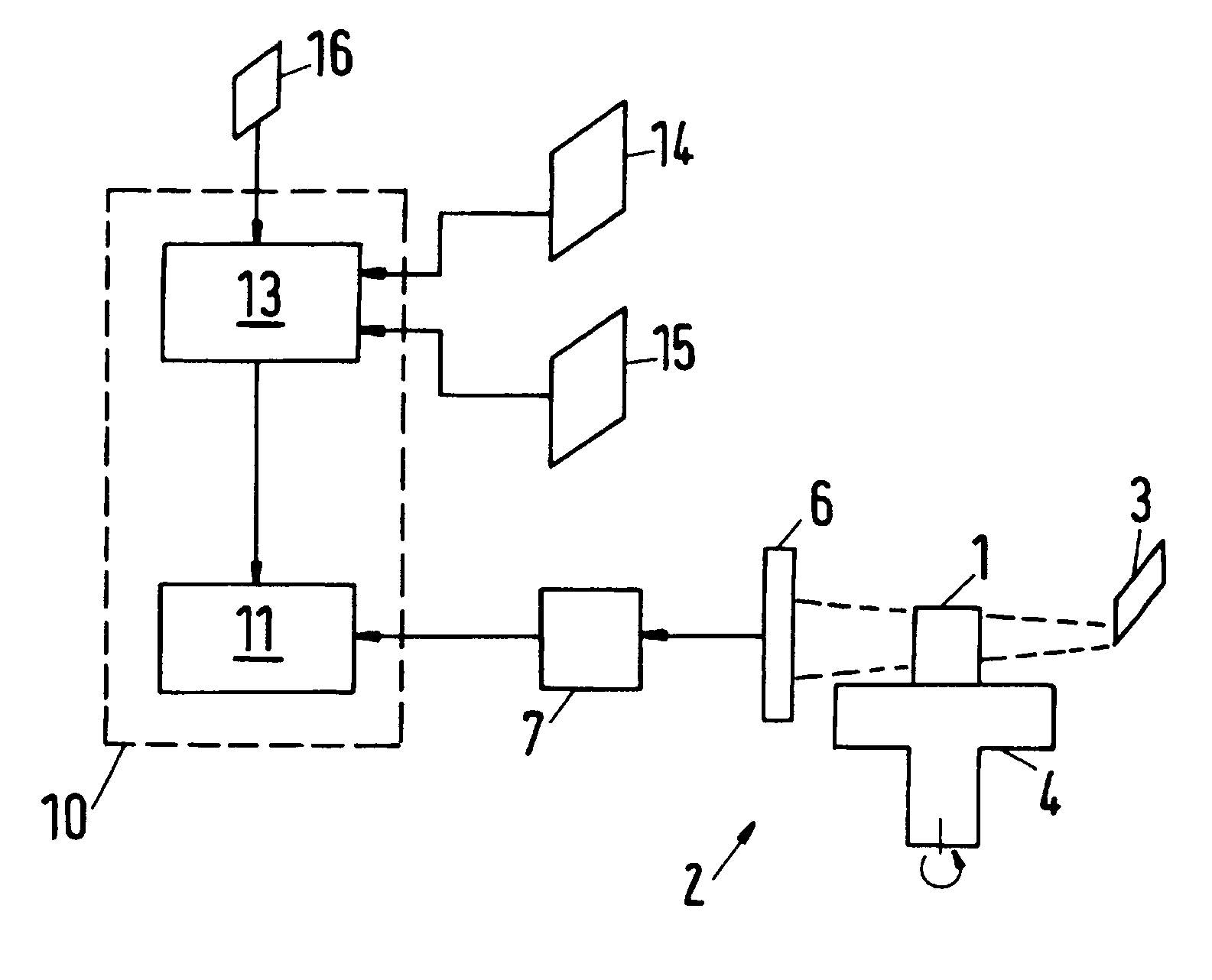
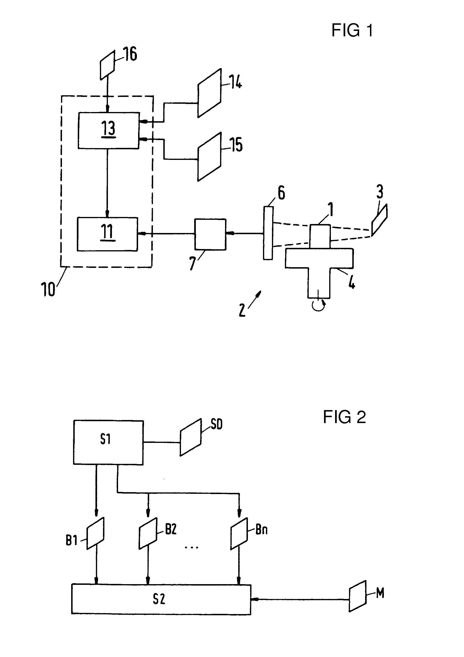
[0059]The configuration illustrated in FIG. 1 has a measuring device 2 that can be used to measure a measurement object 1 by means of invasive radiation.

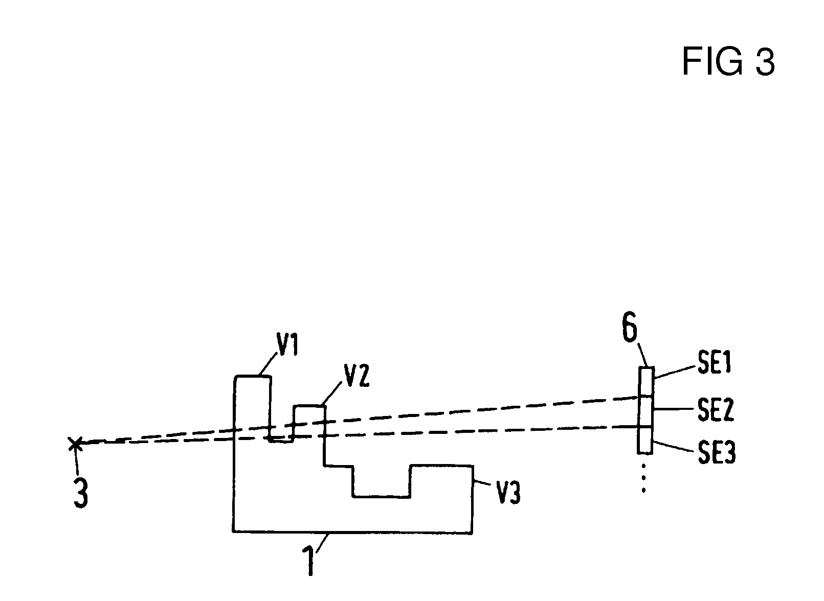
[0060]The measuring device 2 has, for example, an X-ray source 3 for producing X-radiation and for directing a conical X-ray beam onto the measurement object 1. The bounds of the radiation beam are illustrated in FIG. 1 by dashed lines. The X-radiation passes through the measurement object 1 and strikes a sensor device 6 with attenuated intensity. The main reason for the attenuation of the X-radiation is the absorption in the material of the measurement object 1. Furthermore, the X-radiation is scattered in the measurement object 1. In this process, a fraction of the scattered radiation passes once again onto the sensor device 6.

[0061]In the exemplary embodiment, the sensor device 6 comprises an n×m matrix of sensor elements that are sensitive to the X-radiation. Here, n, m are positive integers, and denote the number of rows and co...


PUM


Abstract

A method and an arrangement for investigation of an object to be measured (1), the object to be measured (1) being subjected to invasive radiation. An interaction of the invasive radiation from a radiation source (3) is detected by way of a radiation-sensitive sensor device (6). An anticipated detection result for the sensor device (6) is calculated from a set geometry of the object to be measured (1) and material properties by a calculation (13) and/or an anticipated detection result is determined by measurement of a standard body and the anticipated detection result is compared with an actual detection result from the sensor device (6) by a comparator device (11).

Description

BACKGROUND OF THE INVENTIONField of the Invention[0001]The invention relates to a method and a configuration for examining a measurement object, the measurement object being exposed to invasive radiation, in particular X-radiation.[0002]The use of invasive radiation for examining workpieces is known. In computer tomography (CT), the workpiece is, for example, arranged on a rotary table, and is transirradiated by X-radiation from various directions by rotating the rotary table into various rotational positions. The radiation attenuated by extinction in the material of the workpiece is detected by a sensor device with spatial and time resolution. A spatially three-dimensional model of the workpiece is calculated therefrom by tomographic back projection. The model respectively includes for individual volume regions the material properties for the extinction of X-radiation. DE 39 24 066 A1 describes an example for CT.[0003]The high outlay on measurement and the tomographic back projecti...

Claims


Application Information

Patent Timeline
IPC IPC(8): A61B6/08G01N23/04
CPCG01B15/04G01N23/046G01N2223/419
Inventor ENGEL, THOMAS
Owner CARL ZEISS IND MESSTECHN GMBH
Why Eureka
Try Eureka