
Heat-dissipation structure

a technology of heat dissipation structure and led streetlight, which is applied in outdoor lighting, semiconductor devices of light sources, lighting and heating apparatus, etc., can solve the problems of poor heat dissipation effect of the casing of the streetlight, poor heat dissipation efficiency, so as to improve the heat dissipation structure, improve the heat dissipation effect, and improve the effect of heat dissipation

Inactive Publication Date: 2010-08-10
LI HONG TECHNOLOGICAL
View PDF4 Cites 15 Cited by
  • Summary
  • Abstract
  • Description
  • Claims
  • Application Information

AI Technical Summary

Benefits of technology

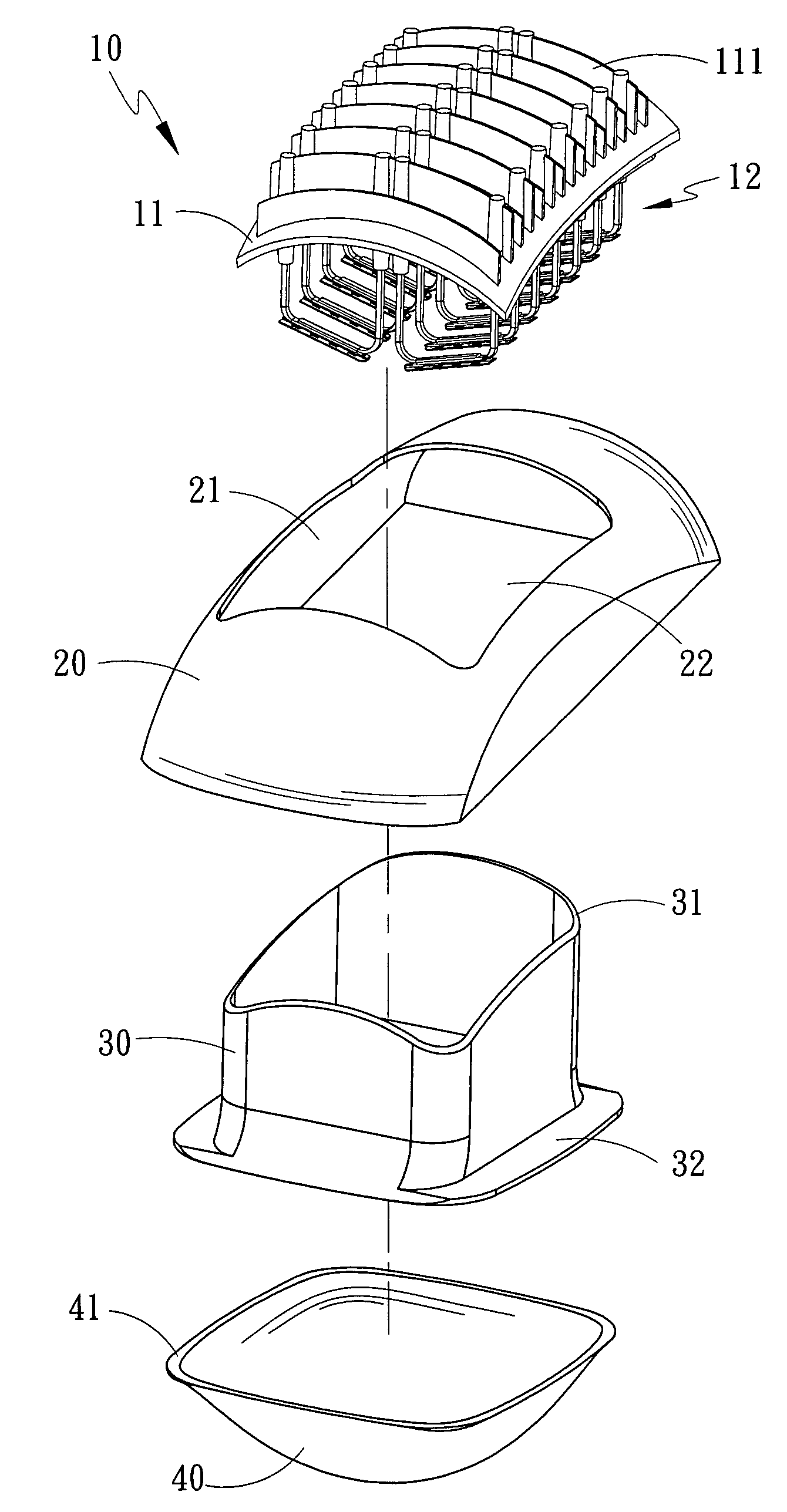
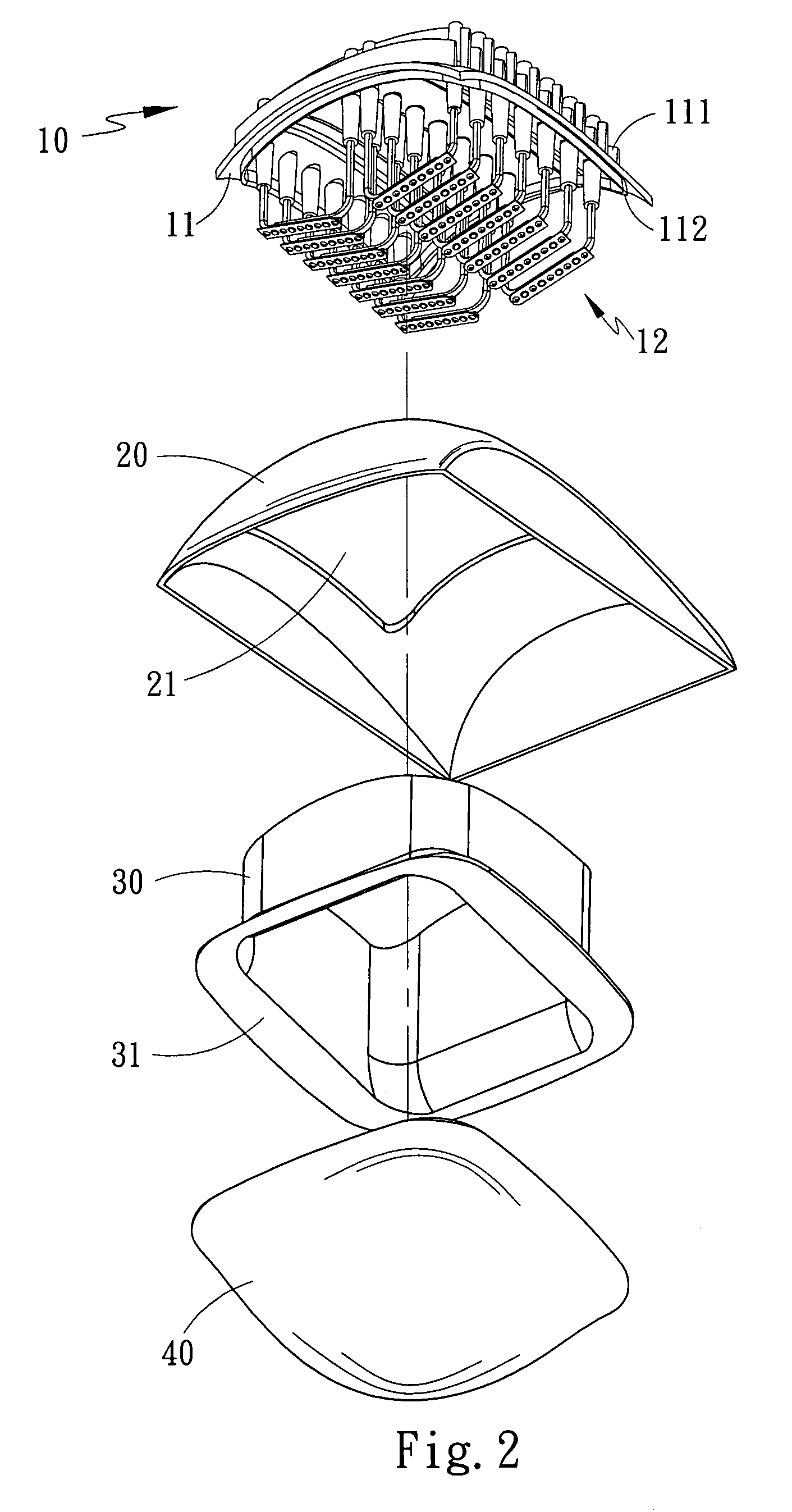
"The present invention provides an improved heat-dissipation structure for streetlights that achieves high brightness, low power consumption, and high heat-dissipation efficiency. The structure includes a heat-dissipation lamp frame with heat-dissipation fins and LED lamp sets, a casing, a light guiding tube, and a light-permeable cover. The heat-dissipation lamp frame has an inlay slot for the light guiding tube, which is a hollow metallic pipe capable of heat conduction. The LED lamp sets are installed in the heat-conduction pipe. The casing has a through-hole to accommodate the heat-dissipation lamp frame, and the light guiding tube passes through the opening and is inlaid in the inlay slot. The light-permeable cover is a light-permeable hood that tightly contacts the flange of the light guiding tube. The dimensions of the through-hole and the opening of the casing are slightly smaller and larger, respectively, to facilitate the installation of the heat-dissipation lamp frame and the light guiding tube."

Problems solved by technology

1. As the conventional streetlight adopts high-brightness and high-power light emitting elements, it has a very amazing power consumption. In such an age that energy is being exhausted, the conventional streetlight is not the best choice.
2. Because of high power consumption, the conventional streetlight generates so much heat that the casing thereof is hard to dissipate heat effectively, which may overheat the casing and burn out the light emitting element.

Method used


Image

  • Heat-dissipation structure
  • Heat-dissipation structure
  • Heat-dissipation structure

Examples


Embodiment Construction

[0022]Refer to FIG. 1, FIG. 2, FIG. 3 and FIG. 4. The improved heat-dissipation structure of the present invention comprises: a heat-dissipation lamp frame 10, a casing 20, a light guiding tube 30 and a light-permeable cover 40. The heat-dissipation lamp frame 10 further comprises: a heat-dissipation structure 11 and a plurality of heat-dissipation lamp sets 12. The heat-dissipation structure 11 has a plurality of heat-dissipation fins 111 on one side thereof, and the heat-dissipation lamp sets 12 are accommodated on the other side of the heat-dissipation structure 11. An inlay slot 112 is formed along the perimeter of the heat-dissipation lamp sets 12 and on the heat-dissipation structure 11 and is used to accommodate the light guiding tube 30. The casing 20 is a metallic shell and has a through-hole 21 on one side thereof to accept the heat-dissipation lamp frame 10. The casing 20 has an opening 22 on the other side thereof. The light guiding tube 30 passes through the opening 22 ...


PUM


Abstract

An improved heat-dissipation structure includes a heat-dissipation lamp frame which comprises: a heat-dissipation structure and a plurality of heat-dissipation lamp sets. The heat-dissipation structure has a plurality of heat-dissipation fins on one side thereof, and the heat-dissipation lamp sets are accommodated on the other side of the heat-dissipation structure. An inlay slot is formed along the perimeter of the heat-dissipation lamp sets and is used to accommodate a light guiding tube which is a hollow and tube-like structure and has an inlay rim. The light guiding tube passes through the opening and is inlaid in the inlay slot of the heat-dissipation lamp frame. A casing is a metallic shell and has a through-hole on one side thereof to accept the heat-dissipation lamp frame. The casing has an opening on the other side thereof. A light-permeable cover is a light-permeable hood and has a contact plane on one side thereof.

Description

FIELD OF THE INVENTION[0001]The present invention relates to an improved heat-dissipation structure, particularly to a heat-dissipation structure for a high-brightness LED streetlight.BACKGROUND OF THE INVENTION[0002]The conventional streetlight usually adopts high-brightness and high-power light emitting elements to achieve high brightness, and the heat is dissipated by the casing of the streetlight. However, the conventional technology has the following disadvantages:[0003]1. As the conventional streetlight adopts high-brightness and high-power light emitting elements, it has a very amazing power consumption. In such an age that energy is being exhausted, the conventional streetlight is not the best choice.[0004]2. Because of high power consumption, the conventional streetlight generates so much heat that the casing thereof is hard to dissipate heat effectively, which may overheat the casing and burn out the light emitting element.SUMMARY OF THE INVENTION[0005]The primary objectiv...

Claims


Application Information

Patent Timeline
Patent Type & Authority Patents(United States)
IPC IPC(8): F21V29/00
CPCF21V29/004F21V29/74F21V29/006F21W2131/103F21Y2101/02F21V29/51F21Y2115/10
Inventor CHANG, KUN-JUNGJUAN, CHING-YUANLIN, KUO-CHUNJUAN, CHING-HUANG
Owner LI HONG TECHNOLOGICAL
Learn More