
Wireless LAN setting system and communication terminal

a technology of communication terminal and wireless lan, which is applied in the direction of wireless commuication services, instruments, and assess restrictions, etc., can solve the problems of unexecuted part of the setting procedure, the connection setting cannot be completed automatically, and the adjustment of the settings through the user interface becomes an extremely complex and troublesome task

Active Publication Date: 2010-08-03
BROTHER KOGYO KK
View PDF44 Cites 52 Cited by
  • Summary
  • Abstract
  • Description
  • Claims
  • Application Information

AI Technical Summary

Benefits of technology

The present invention provides a computer program product for a wireless LAN system that solves the problem of deficiencies in conventional wireless LAN systems. The computer program product allows a second communication terminal to connect with a first communication terminal and make necessary settings for the connection based on the instructions of the first communication terminal. This is done by sending a request to the first communication terminal to make the necessary settings. The first communication terminal determines if it has the necessary functions to make the settings and sends a request for the settings to the second communication terminal. The second communication terminal obtains the necessary settings from the wireless access points around it and sends the settings to the first communication terminal. The computer program product can also include a notifying / confirming procedure that notifies the user of the progress of the connection settings and allows the user to confirm or change them. Overall, the invention provides a more efficient and effective way to set up wireless LAN systems.

Problems solved by technology

However, with communication terminals equipped with a user interface which is less operability than that of a PC (e.g. printers providing services via a network), adjustment of the settings through the user interface becomes an extremely complex and troublesome task.
However, if the target communication terminal does not have a capability, the part of the setting procedure would remain unexecuted.
When such an access point is selected, since a part of the parameters are missing, the connection setting cannot be completed automatically.
That is, if such an access point is included in the list, the user needs to perform the selecting operation again to select another access point since the setting based on the incomplete set of parameters will not work.
It is, however, troublesome to select an appropriate one of the plurality of I / F units.
Further, if a wrong I / F unit is selected, remaining operation of the setting procedure may not be performed or the setting operation man not be completed correctly.

Method used


Image

  • Wireless LAN setting system and communication terminal
  • Wireless LAN setting system and communication terminal
  • Wireless LAN setting system and communication terminal

Examples


first embodiment

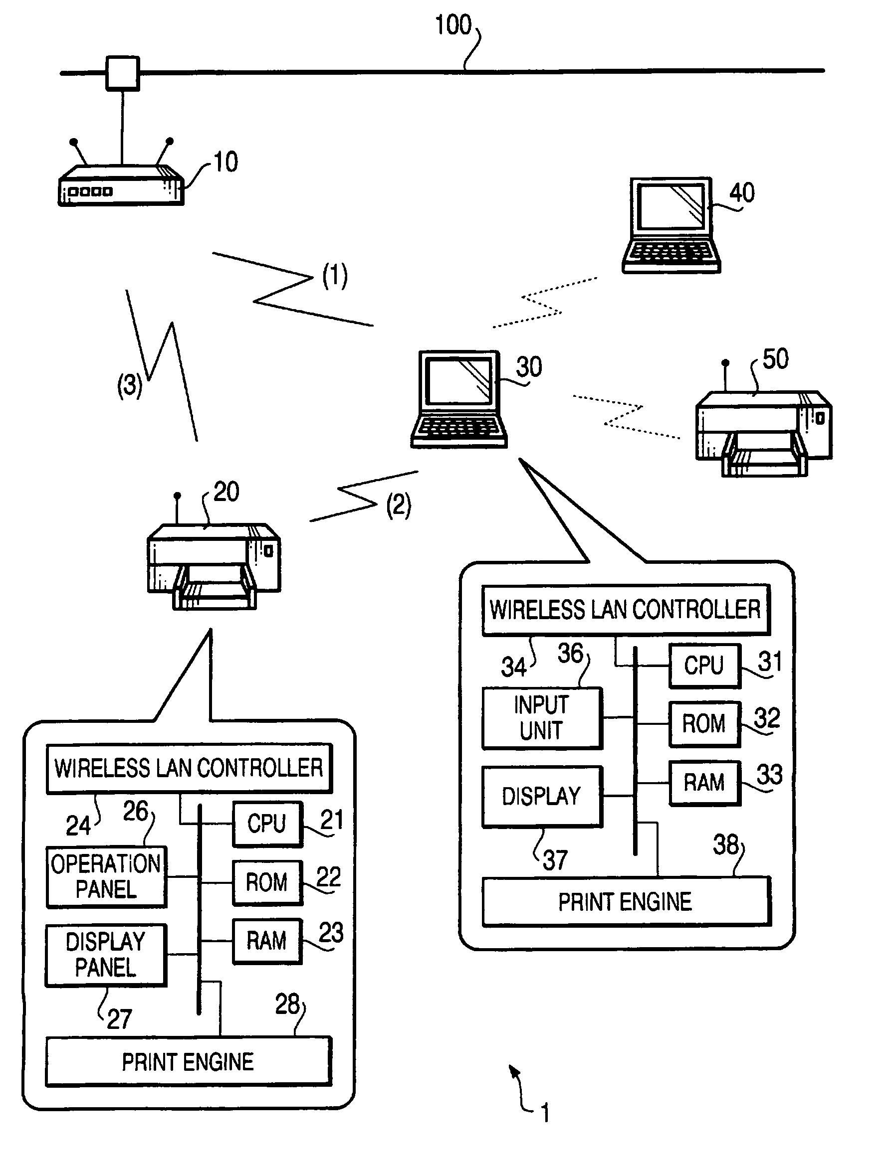
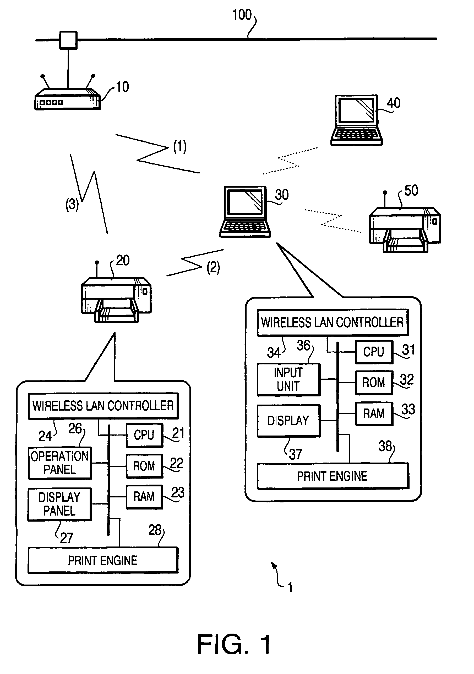
[0143]FIG. 1 shows a network configuration according to a first embodiment of the invention. The network configuration shown in FIG. 1 includes an access point 10, network printers (hereinafter, occasionally referred to simply as printer) 20 and 50, personal computers (PC) 30 and 40, which perform wireless communication with each other.

[0144]The access point 10 is a generally known wireless access point, which relays data communication between other devices (or external networks) connected therewith through the wireless stations and / or a cable 100. The wireless point 10 allows a wireless station that accesses the wireless point 10 using an SSID (Service Set IDentifier) which is the same SSID or ESSID (extended SSID) set to the wireless point 10 (i.e., stored in a not shown memory of the wireless point 10) to communicate as a wireless station.

[0145]When the access point 10 retains a parameter relating to security in its memory, the access point 10 executes the data communication with...

second embodiment

[0362]FIG. 30 shows a configuration of a network system according to the second embodiment. As shown in FIG. 2, the network system includes an access point 10 and a network printer 20 (hereinafter, simply referred to as a printer) which is to be connected to the network, a personal computer (PC) 30 that can change the setting of the printer 20.

[0363]The access point 10 according to the second embodiment is a device complying with one of the wireless LAN standards, IEEE 802.11b / IEEE 802.1 g. The access point 10 operates in the infrastructure mode. The wireless network system is configured such that a plurality of wireless LAN terminals establish wireless communication with the access point 10, which functions as a relaying device.

[0364]The access point 10 is provided with wired LAN interfaces (I / F). Thus, by connecting a LAN cable of a wired LAN system, the wireless LAN and the wired LAN are connected through the access point 10.

[0365]The access point 10 is provided with a non-volati...

third embodiment

[0438]In the third embodiment, a process when the plurality of effective LAN I / F are detected (S224: YES) is different from that of the second embodiment. Thus, in the description below, only the different process will be described.

[0439]FIG. 40 shows a flowchart of the setting procedure according to the third embodiment. Steps S202-S224 of the third embodiment are similar to those of the second embodiment.

[0440]In S224, the PC 30 judges whether there are a plurality of effective LAN I / Fs. If there are a plurality of effective LAN I / Fs (S224: YES), control proceeds to S227 where a user selection procedure is executed.

[0441]FIG. 41 is a flowchart illustrating the user selection procedure (S227 of FIG. 40).

[0442]When the user selection procedure is started, the PC 30 obtains the information from the OS on all the LAN I / Fs which the OS recognizes (S262). Then, the PC 30 displays a LAN I / F selection screen (see FIG. 42) on the display 37 (S264).

[0443]In a LAN I / F selection box 211, info...


PUM


Abstract

A computer program product for a wireless LAN system is configured such that connection settings necessary for a first communication terminal to connect with a wireless access point are made in accordance with an instruction from a second communication terminal, the second communication terminal being capable of performing data communication with the first communication terminal, the computer program product comprising computer readable instructions that cause a computer to function as the second communication terminal, the instructions defining procedures of determining, with performing data communication with the first communication terminal, whether the first communication terminal is capable of realizing a predetermined process regarding the connection settings by itself, and instructing the first communication terminal by sending the instruction for the connection settings to the first communication terminal in accordance with a result of determination made by the determining procedure.

Description

BACKGROUND OF THE INVENTION[0001]The present invention realties to a wireless LAN setting system in which a connection setting of a target communication terminal with respect to a wireless access point is made in accordance with instructions by another communication terminal capable of executing data communication with the target communication terminal.[0002]Nowadays, the so-called wireless LANs realizing data communication among a plurality of wireless stations (communication terminals) or data communication between a wireless station and an external network by use of radio waves, have become widespread.[0003]In the wireless LANs, various communication methods, such as “infrastructure mode” in which each wireless station carries out radio communication (wireless communication) via a repeater station and “ad-hoc mode” in which the communication terminals functioning as wireless stations directly communicate with each other by radio, are employed. Each wireless station, configured to...

Claims


Application Information

Patent Timeline
Patent Type & Authority Patents(United States)
IPC IPC(8): G06F15/177G06F15/16H04W4/00H04L12/28H04W28/18H04W84/18
CPCH04L41/0806H04W8/22H04L41/0213H04L41/0856H04L41/0863H04W12/00H04W28/18H04W48/20H04W84/12H04W12/009H04W12/30H04W12/03
Inventor NOGAWA, HIDEKIKAWAI, SUNAOSEKI, TAKAOIZAKI, TAKESHIKOJIMA, ATSUSHIHIBINO, MASAAKI
Owner BROTHER KOGYO KK
Learn More