Optical fiber and a method for making such

a technology of optical fiber and cladding, which is applied in the field of optical fibers, can solve the problems of high cost, large precision, and high cost of preform components such as the overclad tube and the small glass tube surrounding the core rod(s), and achieve the effects of low cost, high cost and high cos

Inactive Publication Date: 2010-08-03
CORNING INC
View PDF12 Cites 7 Cited by
  • Summary
  • Abstract
  • Description
  • Claims
  • Application Information

AI Technical Summary

Benefits of technology

[0017]An advantage of the method of making fiber according to the present invention is that this method is less expensive than the “stack and draw” process of making a fiber. The stack and draw manufacturing process is a high cost process. There are three high cost elements contributing to the high cost of the stack and draw process. These are: 1) the cost of tubes in the stack, 2) the manual labor associated with assembling the structure, and 3) the overclad tube cost. The exemplary embodiments of the method of making optical fiber according to the present invention advantageously: (i) eliminate one or more (and preferably all three) of these high cost elements, and (ii) are capable of producing large size preforms, which contribute to low cost through high equipment utilization that lowers fixed costs of equipment operators and equipment downtime between set-ups.

Problems solved by technology

PCFs and PBGFs are expensive to make, because in order to propagate light properly, they require a great amount of precision in placement of different preform components (e.g., core rod(s), and the glass tubes surrounding the core rod(s).
The preform components such as the overclad tube and the small glass tubes surrounding the core rod(s) are typically expensive and contribute to the cost of making these fibers.
In addition, PCFs and PBGFs are expensive due to the relatively small amount of fiber resulting per preform assembly (when compared to a standard optical transmission fiber preform making processes), resulting from the relatively small size of the optical preforms.
The stack and draw manufacturing process is a high cost process.
There are three high cost elements contributing to the high cost of the stack and draw process.
These are: 1) the cost of tubes in the stack, 2) the manual labor associated with assembling the structure, and 3) the overclad tube cost.
A fiber drawn or preform blank redrawn with a very low torque could also collapse the interstitial holes, but with the adverse effect of lowering the air-fill fraction created by the tubes.
However, because it is desired that PBG fibers have a high air-filled fraction, low torque (T<10 Nm) draw or re-draw steps are not utilized in manufacturing of PBG fibers.

Method used


Image

  • Optical fiber and a method for making such
  • Optical fiber and a method for making such
  • Optical fiber and a method for making such

Examples


example 1

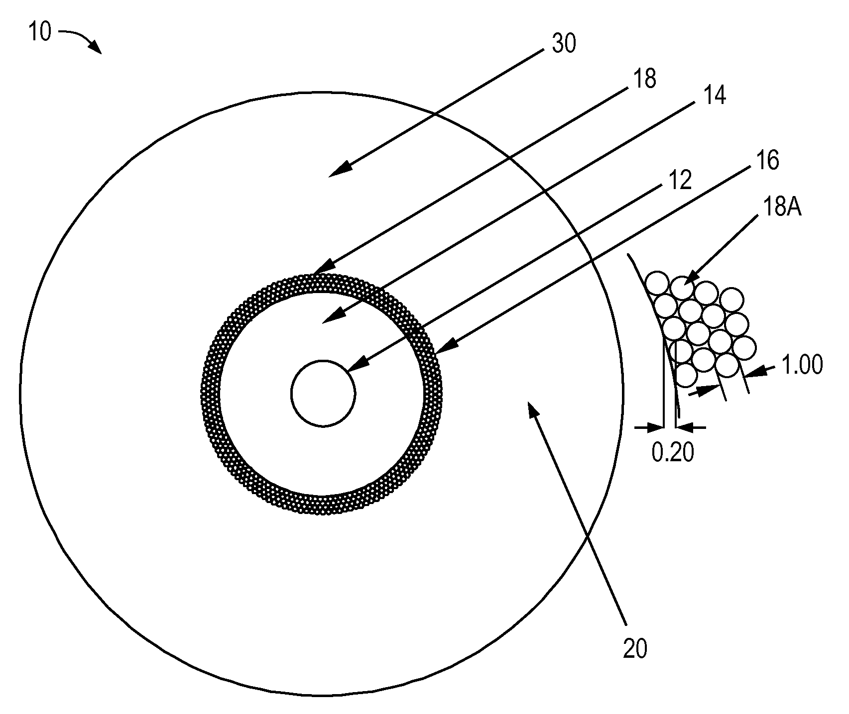
[0062]For example, in order to produce a fiber similar to that of FIG. 1A, the core blank 55 was wrapped in a ribbon 60. The ribbon 60 contained a plurality of glass rods 65A. This ribbon was wrapped around the core blank 50 four times, producing the wrapped preform. The wrapped preform was heated by a flame torch to soften the glass sufficiently so as to tack the rods 65A to each other and to the core blank 55 in order to produce the core blank assembly 70. This core blank assembly was then redrawn to a smaller diameter cane 75, while maintaining the relative interstitial spaces between the glass rods. The cane 75 was than overclad with glass soot (in this example it was pure silica soot, but other dopants may also be present, e.g. chlorine, germanium, fluorine, boron and phosphorus) and consolidated to form the final consolidated glass preform blank 50. It is noted that the soot deposited on the cane 75, after consolidation, corresponds to the cladding 30 of fiber 10 of FIG. 1A.

[0...


PUM

PropertyMeasurementUnit
outer diameteraaaaaaaaaa
temperatureaaaaaaaaaa

Abstract

An optical fiber comprising: (i) a core; (ii) a cladding surrounding the core; wherein the cladding comprises a cladding ring that: (a) has a width W equal to or less than 10 microns; (b) includes at least 50 airlines, each airline having a maximum diameter or a maximum width of not more than 2 microns and more than 50% of said airlines have a length of more than 20 m; (c) has an air fill fraction of 0.1% to 10%, and (d) has an inner radius Rin and an outer radius Rout, wherein 6 μm≦Rin≦14 μm, and 8 μm≦Rout≦14 μm; and (iii) an outer cladding surrounding said cladding ring.

Description

BACKGROUND[0001]1. Field of the Invention[0002]The present invention relates generally to optical fibers, and particularly to optical fibers with airline features, and to a method of manufacturing such fibers.[0003]2. Technical Background[0004]Corning, Inc introduced a new optical fiber, ClearCurve® optical fiber, in 2007. This fiber has improved bend performance due to gas filled voids randomly situated in an annular region surrounding the core of the fiber. The gas filled voids are randomly distributed and are created by trapping gas in the soot during sintering of the preform. The gas filled voids are elongated as the preform is drawn into fiber. These gas filled voids do not extend over the entire length of the fiber and are typically less than 10 m in length.[0005]Photonic crystal fibers and photonic band gap fibers (PCFs and PBGFs) are usually created by a “stack and draw” method. The term “stack and draw” refers to assembling a preform from constituent parts using, for exampl...

Claims


Application Information

Patent Timeline
Patent Type & Authority Patents(United States)
IPC IPC(8): G02B6/032G02B6/02C03B37/027
CPCC03B37/01208C03B37/0124C03B37/014C03B37/02781G02B6/02342C03B2201/31C03B2203/14C03B2203/22C03B2203/42G02B6/0365
Inventor BENNETT, RANDY LEEBICKHAM, SCOTT ROBERTSONCOON, JEFFREYDABICH, II, LEONARD CHARLESHAWTOF, DANIEL WARRENMCCARTHY, JOSEPH EDWARD
Owner CORNING INC
Why Eureka
Try Eureka