
Light source having spatially interleaved light beams

a technology of light beams and interleavers, which is applied in the direction of optics, instruments, optical elements, etc., can solve the problems of reducing the life expectancy of beam combiners before failure, excessive heating, and complicated spatial combiner structure, so as to reduce the heat of the optical interleaver structure, easy to manufacture, and assembled

Active Publication Date: 2010-08-03
RAYTHEON CANADA LTD
View PDF30 Cites 7 Cited by
  • Summary
  • Abstract
  • Description
  • Claims
  • Application Information

AI Technical Summary

Benefits of technology

[0005]The present invention provides a higher-power light source in which the output beams of a number of individual lower-power light sources are combined using a spatial optical interleaver as a beam combiner. The optical interleaver is of a relatively simple design that minimizes fabrication and alignment costs, while also facilitating cooling and minimizing excessive heating of the structure that would otherwise lead to premature failure.
[0010]The present approach interleaves the multiple lower-power source output beams to produce a combined higher-power beam. “Higher” and “lower” are used herein relative to each other—they do not suggest any particular values of power except that one is of higher power than the other. “Combined” means that the individual parallel lower-power source output beams are interleaved and brought closer together to produce separate spatial portions of the higher-power beam, but are not superimposed. The result is that the higher-power beam power has a power that is the sum of the powers of the individual lower-power beams, and has a power density approaching that of the individual lower-power beams and is ideally the same as that of the individual lower-power beams within + / −25 percent, more preferably within + / −10 percent. The present approach achieves the interleaving without the use of expensive multilayer deposited mirror structures. Additionally, heating of the optical interleaver structure is minimized by passing half of the output beams through holes in the structure of the optical interleaver, so that there is no heating of the optical interleaver structure at all from this source. Heating of the optical interleaver structure is otherwise potentially a major cause of premature failure. The optical interleaver structure also may be artificially cooled. The optical interleaver is readily manufactured, assembled, and aligned with the beam sources, and the alignment is maintained during service.

Problems solved by technology

This approach is operable to a degree, but has drawbacks.
The structure of the spatial combiner is complicated and expensive to produce.
There may be excessive heating of the beam combiners as the numerous lower-power light beams pass through them, reducing the life expectancy of the beam combiners before failure.
In another approach, light beams may be combined with polarization combiners, which require polarization of the light beams and also are subject to excessive heating.

Method used


Image

  • Light source having spatially interleaved light beams
  • Light source having spatially interleaved light beams
  • Light source having spatially interleaved light beams

Examples


Embodiment Construction

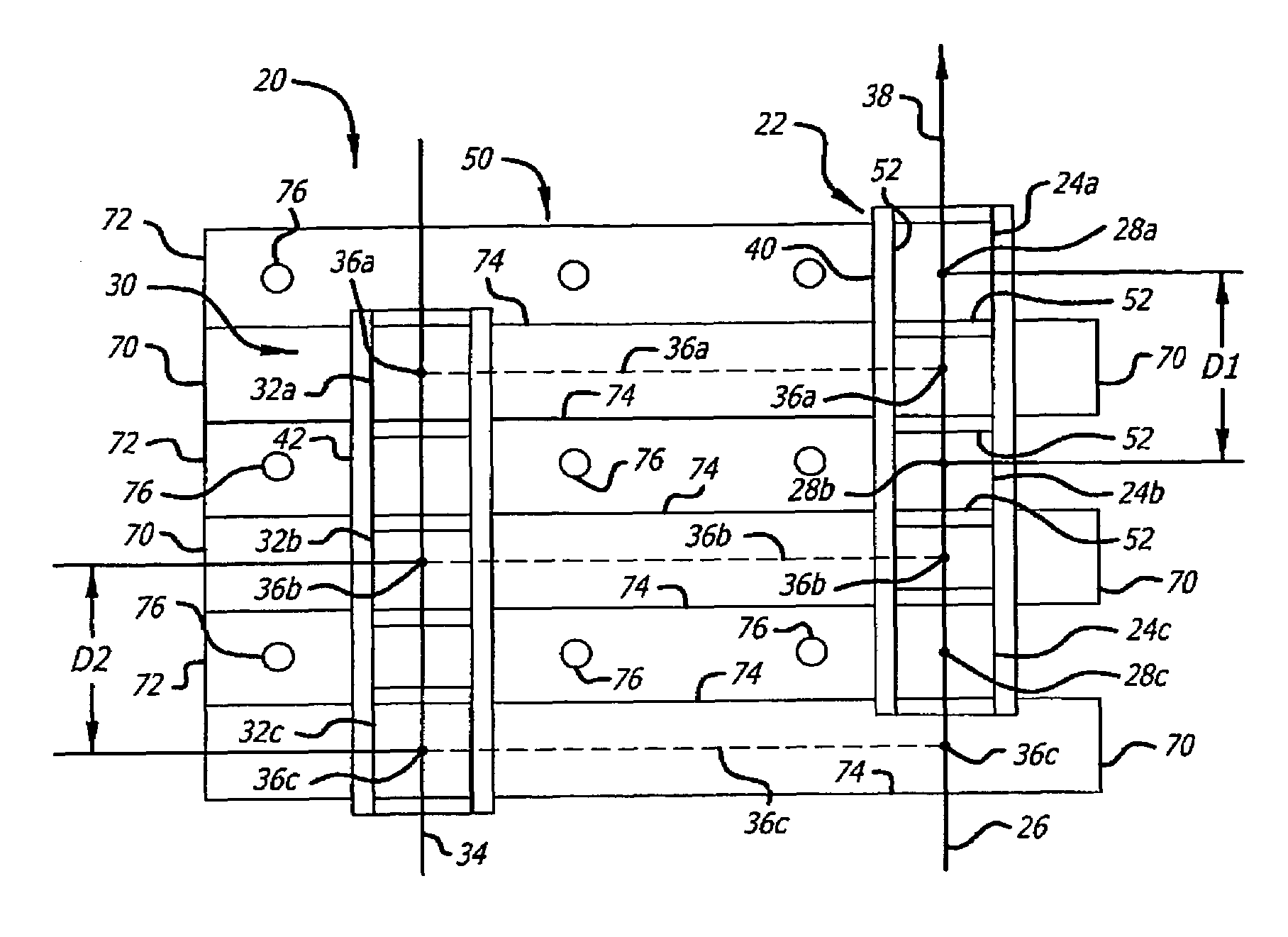
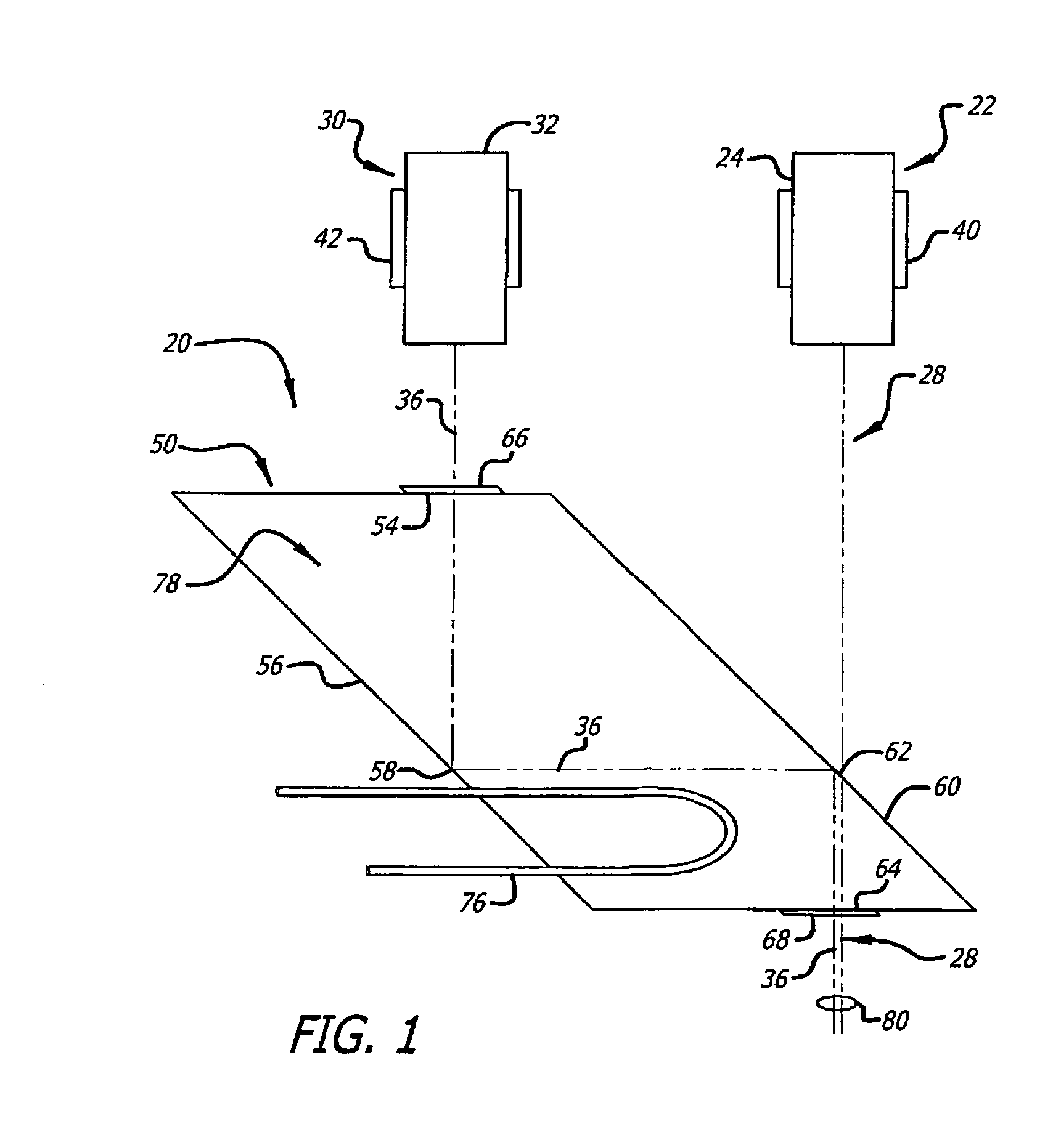
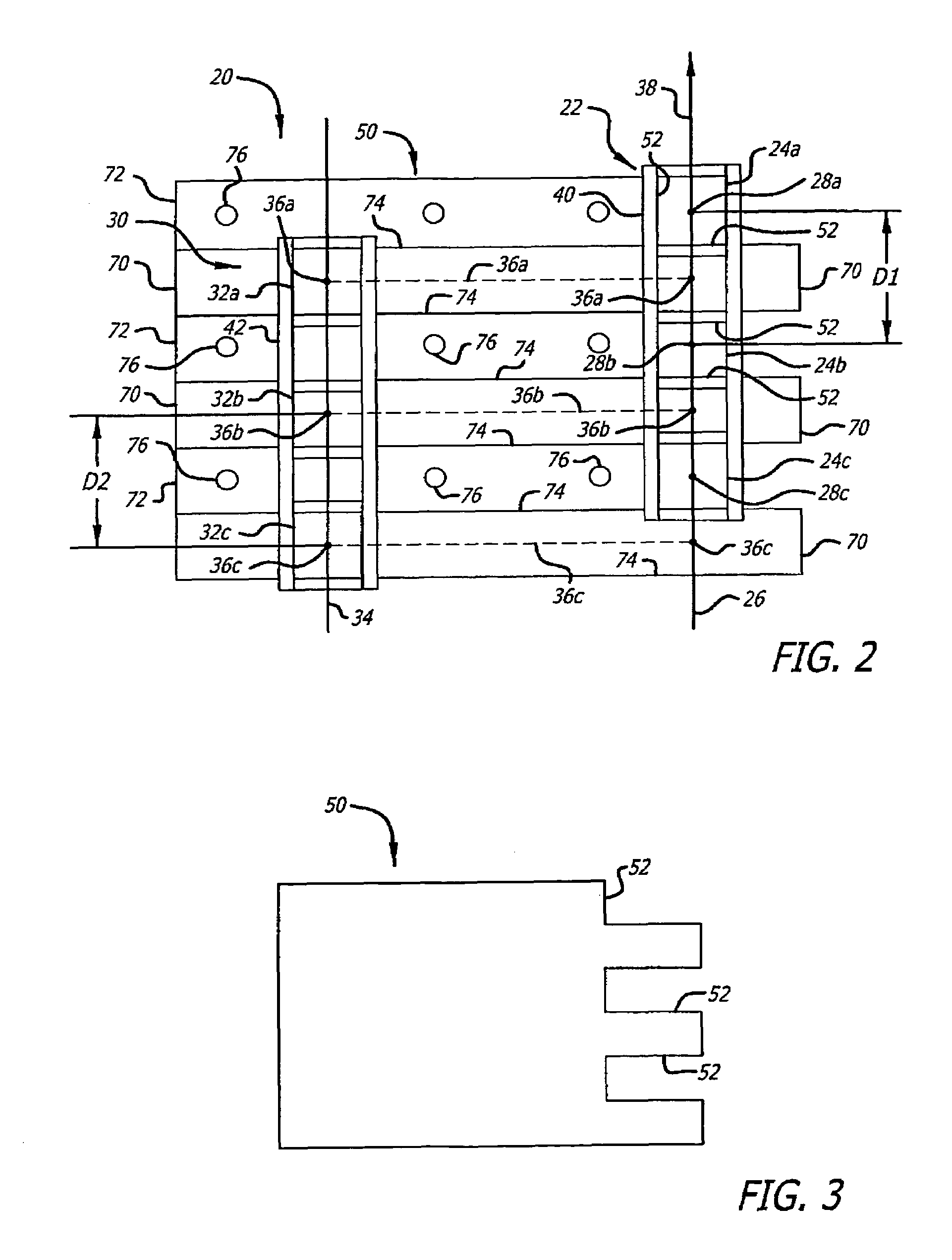
[0015]FIGS. 1-2 schematically depict a first embodiment of a light source 20 according to the present approach, illustrating its structure and principles of operation. FIG. 1 is a plan view, and FIG. 2 is the corresponding front elevational view. Not all of the elements are visible in FIG. 1, because some elements lie directly below the illustrated elements.

[0016]The light source 20 comprises a first set 22 of first beam sources 24. In this case, the first set 22 of first beam sources 24 includes three first beam sources 24a, 24b, and 24c. The first beam sources 24 lie in a stacked arrangement in a first-beam-source plane 26 and are spaced apart by a first-source distance D1 (which may be the same for each pair of the first beam sources 24 or may be different for different pairs of the first beam sources 24). Each of the first beam sources 24 has a first-beam-source output beam 28, specifically the respective first-beam-source output beams 28a, 28b, and 28c (represented by dots in F...


PUM


Abstract

A light source includes a first set of first beam sources having parallel output beams lying in a first-beam-source plane and a second set of second beam sources having parallel output beams lying in a second-beam-source plane. The first-beam-source output beams are parallel to the second-beam-source output beams, but are spatially offset in a direction perpendicular to the first-beam-source output beams. A spatial optical interleaver disposed receives the first-beam-source output beams and the second-beam-source output beams. The first-beam-source output beams pass unimpeded through a set of first-beam openings in the spatial optical interleaver, and the second-beam-source output beams are reflected parallel to the first-beam-source output beams and in the first-beam-source plane.

Description

[0001]This invention relates to a light source in which the output beams of a number of individual beam sources of lower power are interleaved and thence combined to form a high-power light beam.BACKGROUND OF THE INVENTION[0002]One approach to creating a light source with a very high output power is to combine the individual output beams of a number of lower-power light sources such as lasers or light-emitting diodes. The combination of the individual output beams is accomplished spatially. That is, the individual output beams are supplied to a beam combiner, and the beam combiner directs the individual output beams in a parallel fashion through a small cross-sectional area to create the high-power beam. This approach also allows the individual lower-power light sources to be spaced apart to facilitate their cooling.[0003]The existing beam combiners typically use spatial combiners having an optical surface whose properties are different in different areas. For example, the spatial c...

Claims


Application Information

Patent Timeline
Patent Type & Authority Patents(United States)
IPC IPC(8): G02B27/14G02B27/10
CPCG02B27/1006G02B27/126
Inventor HARRIS, GEOFFREY G.MITCHELL, DANIELSCOTT, BOB
Owner RAYTHEON CANADA LTD
Learn More