Plugging system for use during an offshore pipeline laying operation

a technology for offshore pipelines and plugging systems, which is applied in the direction of pipe laying and repair, pipe/joints/fittings, mechanical equipment, etc., can solve the problems of pipe loss, further damage, and loss of all or part of the buoyancy of the pip

Active Publication Date: 2010-08-03
TDW OFF SHORE SERVICE CO LTD
View PDF21 Cites 6 Cited by
  • Summary
  • Abstract
  • Description
  • Claims
  • Application Information

AI Technical Summary

Benefits of technology

[0011]As mentioned above, the greatest stresses experienced by the pipe during laying are found in those portions where it experiences the greatest bending stress. These are the portions where there is a risk of leakage. By arranging an upper plug internally in the pipe immediately below the bend behind the lay vessel, referred to as the upper bend, and a lower plug immediately above the bend at the seabed, referred to as the lower bend, any inflow of water through a damaged part of the pipe can be prevented from filling a pipe section between the upper and the lower bends, hereinafter called the intermediate pipe section.
[0012]If a leakage were to occur in the upper bend, the water is prevented from penetrating into the intermediate pipe section by the upper plug being locked in the pipe and providing a seal, or alternatively being held in place by a line running between the upper plug and an attachment point in the lay vessel.
[0013]Correspondingly, if a leakage was to occur in the lower bend or in the portion of the pipe situated on the seabed, the lower plug is locked into the pipe, providing a seal, whereby water is prevented from penetrating up and into the intermediate pipe section.

Problems solved by technology

When laying pipes at great depths, the mass of the section of the pipe located between the lay vessel and the seabed represents a considerable weight.
Instances are known where pipes have not been able to bear the stress to which they are subjected during laying, resulting in leakages.
Such leakages may be due to defects in the welding or the material, or a stability problem may occur, which causes the pipe to collapse over a certain distance, creating 25 longitudinal cracks.
When a leakage occurs and the pipe fills with water, the pipe loses all or part of its buoyancy.
Such leakages may have catastrophic consequences, in that the net weight of that portion of the pipe which is located in the sea between the lay vessel and the seabed exceeds the bed capacity of the lay vessel This may cause the pipe to detach from the production equipment on the lay vessel and fall down to the seabed, thus incurring further damage.
It may also damage the vessel seriously.
Obviously, such an unintended event or accident involves a great risk of personal injury and material damages.
Many known plugs will not react quickly enough and also possibly not give a satisfactory grip on the wall of the pipeline, and the plug may therefore slip in relation to the pipeline and therefore not seal off the pipe, which then gives an unsatisfactory security of the system.

Method used


Image

  • Plugging system for use during an offshore pipeline laying operation
  • Plugging system for use during an offshore pipeline laying operation
  • Plugging system for use during an offshore pipeline laying operation

Examples


Embodiment Construction

[0031]It is to be understood that the invention that is now to be described is not limited in its application to the details of the construction and arrangement of the parts illustrated in the accompanying drawings. The invention is capable of other embodiments and of being practiced or carried out in a variety of ways. The phraseology and terminology employed herein are for purposes of description and not limitation.

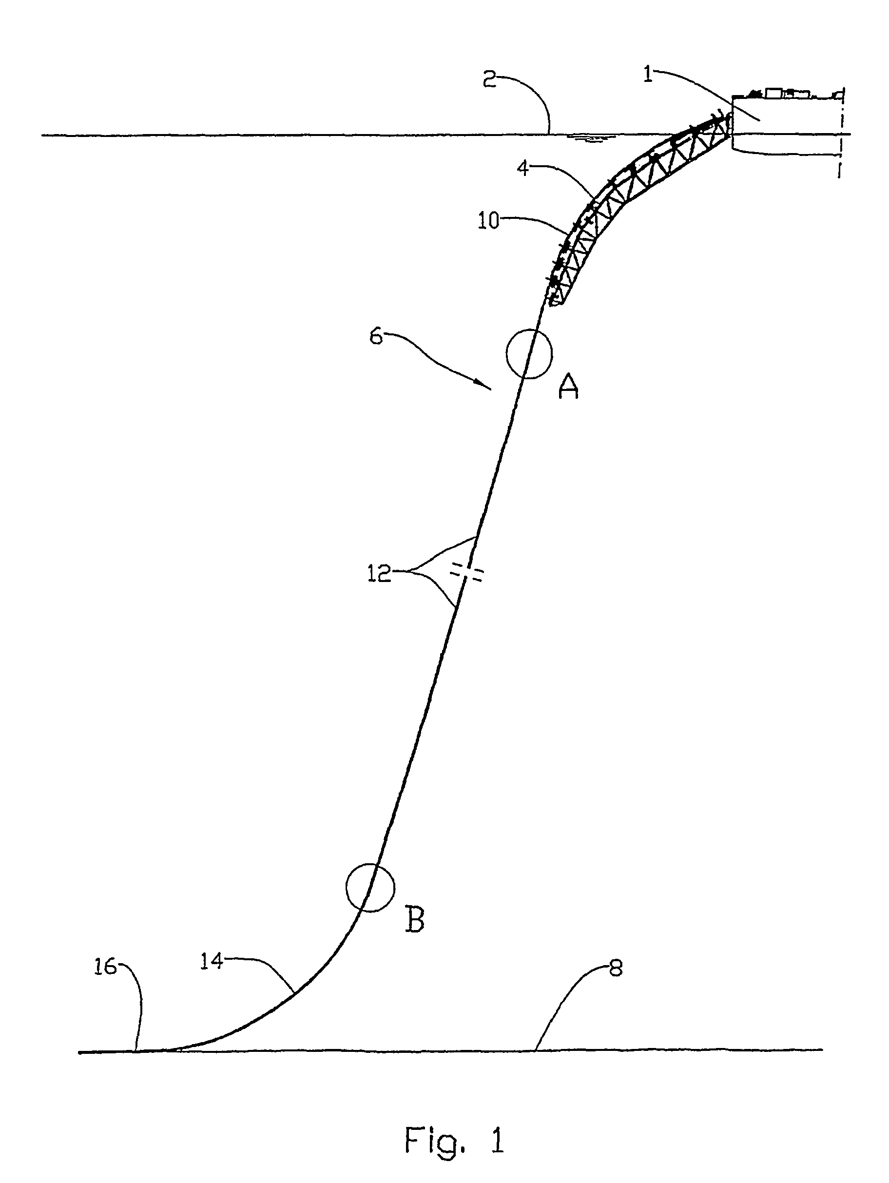
[0032]In the drawings, reference number 1 denotes a pipelay vessel on the surface of the sea 2, where the pipelay vessel 1 is equipped with a stinger 4 for laying of a pipe 6 on the seabed 8.

[0033]While being fed across the stinger 4, the pipe 6 is subjected to bending in the downward direction, thereby forming an upper bend 10. Below the upper bend 10, the pipe runs as an intermediate pipe section 12, essentially in a straight line to a lower bend 14. The lower bend 14 is formed at the transition between the intermediate pipe section 12 and the portion 16 of the pipe 6...


PUM


Abstract

A plug for use during a pipeline laying operation for sealing off sections of the pipeline in case of water ingress. A sealing and gripping assembly is formed of slip segments around a partially conical shaped surface, the slip segments being moved by a piston / cylinder arrangement. A valve connected to a pressure vessel actuates the piston / cylinder in response to the detection of conductivity of fluid around the plug.

Description

REFERENCE TO PENDING APPLICATIONS[0001]This application is a continuation-in-part patent application claiming priority to U.S. patent application Ser. No. 10 / 494,727, filed on May 26, 2004 entitled “Method and Device For Increasing Safety During Pipelaying”. This patent application will issue as U.S. Pat. No. 7,210,503 on May 1, 2007.FIELD OF THE INVENTION[0002]This invention relates to a device for use in laying a pipeline on the bottom of a seabed at great depths and specifically for closing the interior of the pipeline in the event leakage occurs as it is being laid to prevent the entry of sea water therein and to thereby ensure that excess weight is not transferred to the lay vessel.BACKGROUND OF THE INVENTION[0003]When laying pipelines on the seabed by means of a pipelay vessel where the pipeline is welded together from lengths of pipe, the pipe is normally laid in a dry state. This means that the pipe is full of air or another gas during laying.[0004]According to known techniq...

Claims


Application Information

Patent Timeline
Patent Type & Authority Patents(United States)
IPC IPC(8): F16L55/10F16L1/20F16L1/235
CPCF16L1/20F16L1/235
Inventor SYSE, HARALDALEKSANDERSEN, JOSTEIN
Owner TDW OFF SHORE SERVICE CO LTD
Why Eureka
Try Eureka