
Communication system, communication device and flow control based on status information of data buffer usage

a communication system and data buffer technology, applied in the field of communication devices, can solve the problems of maximum value, difficult to deal with conventional spi-4 interfaces, and inability to give priority to fifo information, so as to eliminate the dependency of the worst response time, the utilization efficiency of the data buffer (fifo buffer) can be improved, and the worst response time can be worst.

Inactive Publication Date: 2010-07-27
RENESAS ELECTRONICS CORP
View PDF4 Cites 4 Cited by
  • Summary
  • Abstract
  • Description
  • Claims
  • Application Information

AI Technical Summary

Benefits of technology

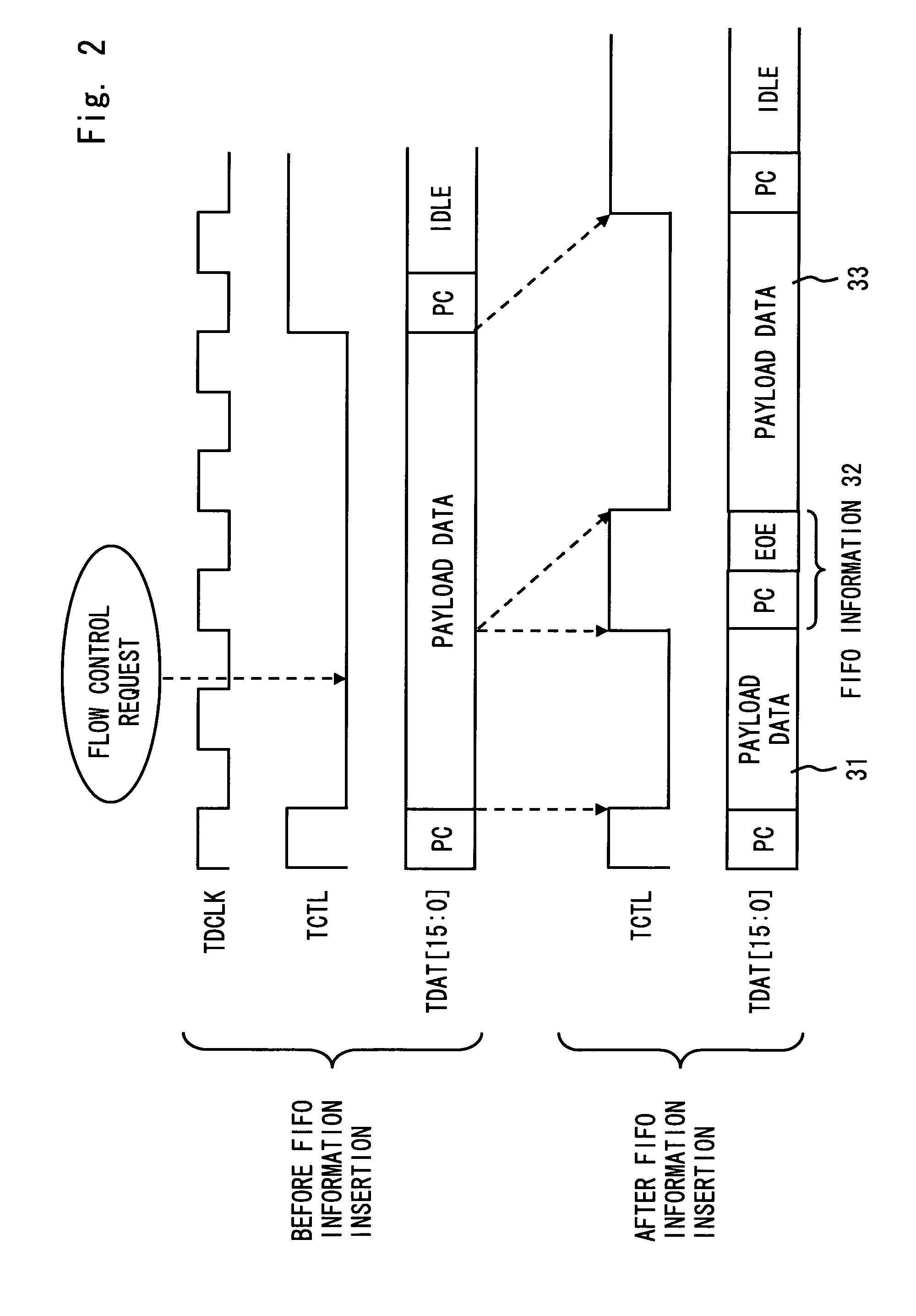
The patent text describes a communication system that can prioritize the transmission of buffer status information in a communication system complying with the SPI-4 Phase 2 standard. This is done by inserting the buffer status information between the payload data based on its priority and outputting it to the first data channel, which allows for quicker flow control and improved utilization efficiency of the data buffer. Additionally, the system eliminates the dependency of the worst response time on the calendar length, ensuring efficient data transmission.

Problems solved by technology

There are two problems described below in the flow control using the FIFO information in the conventional SPI-4 interface.
The first problem is that priorities cannot be given to FIFO information.
Therefore, the conventional SPI-4 interface is difficult to deal with an urgent transmission request of FIFO information which is generated unexpectedly.
The second problem is that as the calendar length increases, a maximum value (hereinafter referred to as worst response time) of time required from a generation of a status change of the FIFO buffer until a flow control is performed by an opposing device also increases.
The longer the worst response time, the lower the second threshold AF must be specified, thus the abovementioned second problem causes to reduce utilization efficiency of the FIFO buffer.

Method used


Image

  • Communication system, communication device and flow control based on status information of data buffer usage
  • Communication system, communication device and flow control based on status information of data buffer usage
  • Communication system, communication device and flow control based on status information of data buffer usage

Examples


first embodiment

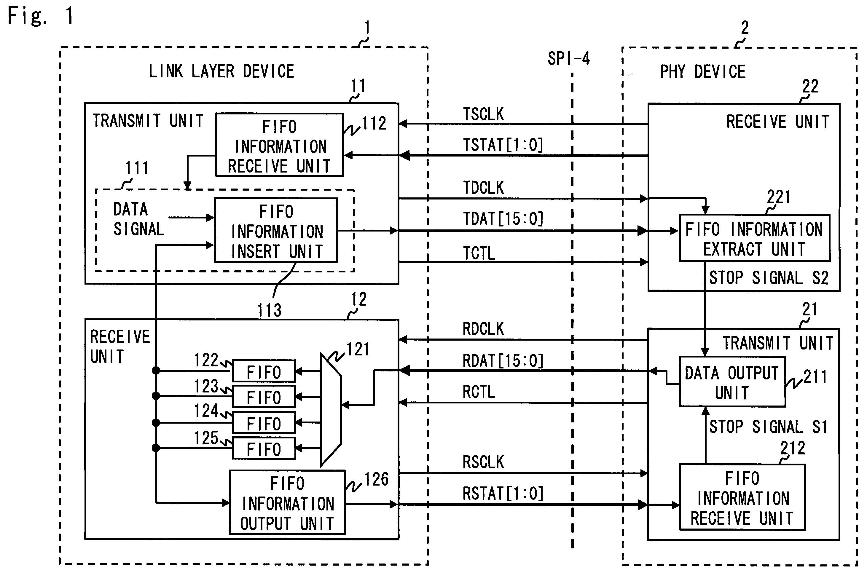
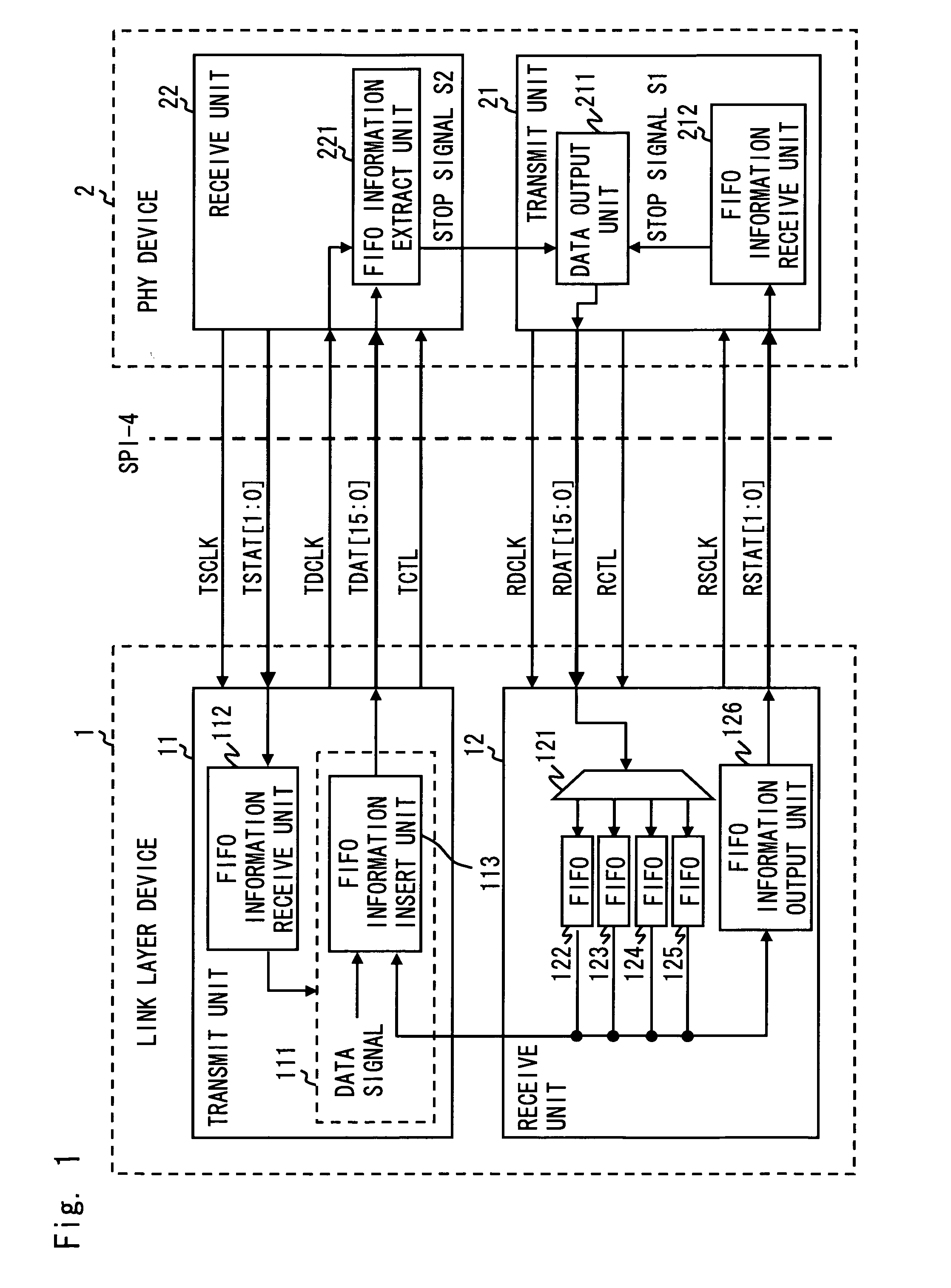
[0044]A block diagram of a communication system according to this embodiment is shown in FIG. 1. The communication system shown in FIG. 1 includes a link layer device 1 and a PHY device 2 which are connected by the SPI-4 interface improved by the present invention.

[0045]The link layer device 1 includes a transmit unit 11 and a receive unit 12. Each of a receive data distribution unit 121, FIFO buffers 122 to 125 and a FIFO information (buffer status information) output unit 126 included in the receive unit 12 may be the same as the components included in the abovementioned receive unit 72 of a related art.

[0046]A data output unit 111 included in the transmit unit 11 is the same as the data output unit 711 included in the transmit unit 71 of a related art in the points that payload data and a control word is output to TDAT and data output is suspended in response to a stop signal output from a FIFO information (buffer status information) receive unit 112. In addition to these, the da...

second embodiment

[0061]In the first embodiment of the present invention, urgent FIFO information which is generated unexpectedly is transferred using the data channels (TDAT and RDAT). Instead of or in addition to the operation of the first embodiment of the present invention, FIFO information can be periodically transferred using the data channels (TDAT and RDAT).

[0062]FIG. 7 is a waveform chart showing an example of transferring FIFO information periodically using the data channels (TDAT and RDAT). If the transmit order of the FIFO information is determined beforehand, it is not necessary to collectively transfer a FIFO address when transmitting FIFO information periodically. That is, as shown in FIG. 7, all of the 4th bit to the 11th bit of a control word which can be used for transferring FIFO information can be used to transfer FIFO accumulation information. In the example of FIG. 7, the number of bits of FIFO accumulation information for indicating the usage status of each FIFO buffer is 2 bit...


PUM


Abstract

A communication system complying with SPI-4 Phase 2 standard includes a local device, an opposing device, a first data channel to transfer payload data from the local to the opposing device, a second data channel opposed to the first data channel, and a first status channel to be able to transfer data from the local to the opposing device. The local device periodically outputs buffer status information of a data buffer for storing payload data received over the second data channel to the first status channel. Further, the local device inserts the buffer status information between the payload data according to a priority of the buffer status information in order to output the buffer status information to the first data channel. The opposing device controls to output payload data to the second data channel according to the buffer status information received over the first status channel and the first data channel.

Description

BACKGROUND OF THE INVENTION[0001]1. Field of the Invention[0002]The present invention relates to communication devices, and especially to communication devices for performing flow control with an opposing communication device.[0003]2. Description of Related Art[0004]In order to ensure interconnectivity between communication devices which are manufactured by different manufacturers, there is SPI-4 Phase 2 standard as a communication interface standard defined by OIF (Optical Internetworking Forum). The details of the SPI-4 Phase 2 standard are specified in “System Packet Interface Level 4 (SPI-4)” 15 Oct. 2003. Hereinafter, communication interface specified by the SPI-4 Phase 2 standard is referred to as SPI-4 interface.[0005]The SPI-4 interface is an interface specified in order to interconnect a link layer device and a PHY device (see for example U.S. Pat. No. 6,522,271). A block diagram of a link layer device and a PHY device connected by the SPI-4 interface is shown in FIG. 8. Th...

Claims


Application Information

Patent Timeline
Patent Type & Authority Patents(United States)
IPC IPC(8): G06F3/00H04L47/30
CPCG06F5/12G06F2205/126
Inventor IIMA, TOMOFUMI
Owner RENESAS ELECTRONICS CORP
Learn More