
Connector assembly for termination of miniature electronics

a technology for connecting assemblies and miniature electronics, applied in the direction of semiconductor devices for light sources, coupling device connections, lighting and heating apparatus, etc., can solve the problems of providing these devices with higher current ratings, longer mean life ratings and usage, etc., to prevent heat build-up, simplify assembly, and high-power led assembly

Inactive Publication Date: 2010-07-27
TE CONNECTIVITY CORP
View PDF5 Cites 11 Cited by
  • Summary
  • Abstract
  • Description
  • Claims
  • Application Information

AI Technical Summary

Benefits of technology

The present invention provides connectors and connector assemblies for use with miniature electrical components, specifically miniature LEDs. These connectors and connector assemblies offer a reliable mechanical connection that eliminates the need for soldering and provides a higher current rating and longer mean life rating for the miniature electronic components. The heat sinks in the connectors prevent heat build-up and allow the miniature electronics to operate at a lower temperature or with higher power requirements. The assembly is simplified as the connection between the connector and the miniature electronic device is a simple mechanical connection. The invention also allows for the mounting of high power LED assemblies with heat sinks remotely from the driver electronics, allowing the light output to be directed where it is needed.

Problems solved by technology

In addition, the heat sinks reliably remove heat, thereby providing these devices with higher current ratings and longer mean life ratings and usage.

Method used


Image

  • Connector assembly for termination of miniature electronics
  • Connector assembly for termination of miniature electronics
  • Connector assembly for termination of miniature electronics

Examples


second embodiment

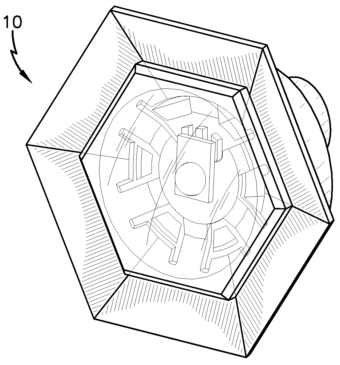
[0032]the present invention is depicted in FIGS. 4-11. This embodiment is the LED stamped connector assembly 100 comprising a Carclo lens 110 assembled to a thermoplastic lens carrier 112, which is assembled over a heat sink assembly 120. An exploded view of LED stamped connector assembly 100 is depicted in FIG. 5. Heat sink assembly 120, shown in FIG. 6 is comprised of stamped heat sink 126 through which is mounted a plastic contact carrier 128 into which is assembled compliant power contacts 130, more clearly visible in FIGS. 8 and 10. A contact carrier assembly 129 comprising the compliant power contacts 130 assembled into the plastic contact carrier 128 is shown in FIG. 7. The contact carrier assembly 129 snaps into the aperture pattern on the top face of stamped heat sink 126 as shown in FIG. 8. An LED 124 is positioned into a locator pocket molded into plastic contact carrier 128, as depicted in FIG. 9. Referring back to FIGS. 5 and 6, a retention clip 122, preferably of stain...

third embodiment

[0036]FIGS. 13 and 14 depict the present invention. An LED connector heat sink assembly 150 is depicted in FIG. 13. The back end of the LED connector heat sink assembly 150 is shown in FIG. 14. The back end 152 is a Mini-CT connector-compatible, permitting a Mini-CT connector to be inserted into the back end 152.

[0037]An exploded view of the LED connector heat sink assembly 150 is depicted in FIGS. 15A and 15B. Connector heat sink assembly 150 comprises a miniaturized LED 154, such as the Rebel LED discussed previously. The miniaturized LED 154 is inserted into and positioned in heat sink body 156 and is held in place by contact cartridge assembly 158. An optional mounting nut 160 having threads 162 may be threaded over optional mating threads 164 on the exterior of heat sink body 156, to mount the connectorized heat sink to a panel.

[0038]Contact cartridge assembly 158 is depicted in FIG. 16, and in exploded view in FIG. 17. Contact cartridge assembly 158 includes a plastic cartridg...


PUM

PropertyMeasurementUnit
forceaaaaaaaaaa
thermally conductiveaaaaaaaaaa
mechanical strengthaaaaaaaaaa

Abstract

Connector and connector assemblies for use with miniature high power electrical components, and specifically with miniature LEDs. Although the connectors and connector assemblies are designed for use with miniature LEDs, these devices are not so limited and can also be used with other miniature electronic devices. These connectors and connector assemblies provide a mechanical connection between the miniature electronic component and electrical contacts instead of a soldered connection, providing a reliable electrical contact between the component, whether used in a PCB-type drop-in connection or some other connection. The connector also includes a heat sink to remove heat from the connector assembly generated by the LED and provides for a reliable mechanical connection between the LED and heat sink.

Description

FIELD OF THE INVENTION[0001]The present invention is directed to connector assemblies for miniature electronics, and specifically, to connector assemblies for use with miniature LEDS that include heat sinks.BACKGROUND OF THE INVENTION[0002]Light emitting diodes (LEDs) are used in a variety of applications and one class of these LEDs has been shrunk so that they can be used in miniature electronics, such as in surface mount applications. These miniature high power LEDs are assembled onto connectors or printed circuit boards (PCBs) as drop-ins, which are then soldered using reflow techniques to provide electrical contact. Difficulties can be encountered with soldering, as reflow can result in poor connections. But soldering also adds processing costs and complexity.[0003]These assemblies are also limited with respect to the amount of heat that can be generated, as these assemblies do not incorporate heat sinks and heat dissipation capabilities are limited. The design operating tempera...

Claims


Application Information

Patent Timeline
Patent Type & Authority Patents(United States)
IPC IPC(8): H01R13/625F21K99/00
CPCF21K9/00F21V17/18F21V29/89F21V23/06F21V29/505F21V29/74F21V17/16F21V19/0025F21Y2115/10F21V7/28
Inventor DAILY, CHRISTOPHER GEORGEGINGRICH, III, CHARLES RAYMONDBUCHER, ALAN WEIR
Owner TE CONNECTIVITY CORP
Learn More