
Light amount adjustment apparatus and image pickup apparatus

a pickup apparatus and light amount technology, applied in the direction of instruments, horology, magnetic circuit shape/form/construction, etc., can solve the problems of excessive restoring force and plastic deformation of the core, and achieve the stabilization of the attaching state of the core to the base member, the effect of improving the positional accuracy between the magnet and the cor

Inactive Publication Date: 2010-07-20
SONY CORP
View PDF14 Cites 6 Cited by
  • Summary
  • Abstract
  • Description
  • Claims
  • Application Information

AI Technical Summary

Benefits of technology

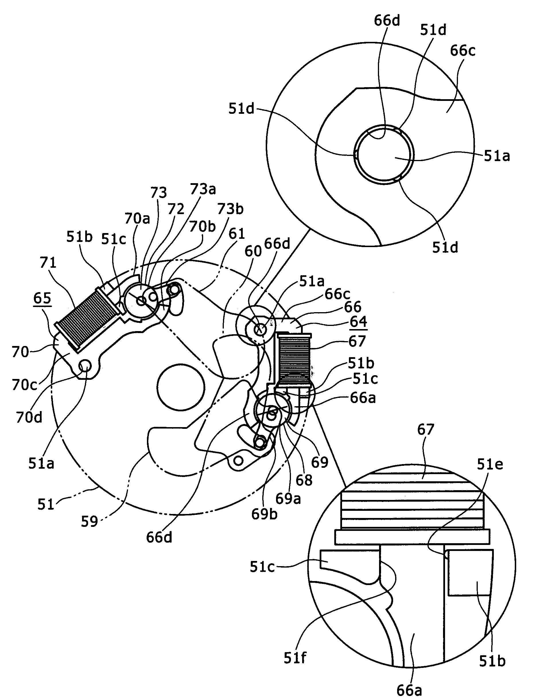
The present invention provides a light amount adjustment apparatus and an image pickup apparatus that can prevent play of the core with respect to the base member without raising the working accuracy of pertaining elements relating to the attachment of the core to the base member. The apparatus includes a light amount adjustment member, a rotatable magnet, a driving arm, a core with a pair of confronting portions, a connecting portion, a coil, and a base member with attaching projections. The core is attached to the base member in a state wherein it is force fitted between the attaching projections with the small protrusion of the attaching projections pressed against the core. The apparatus can stabilize the attaching state of the core to the base member and improve the positional accuracy between the magnet and the core. The apparatus can be used in a light amount adjustment and image pickup apparatus.

Problems solved by technology

However, in the light amount adjustment apparatus disclosed in Patent Document 1, since the electromagnet is attached to the base member in such a state that the paired confronting portions of the core are expanded by the positioning projection, there is the possibility that the core may be deformed plastically or excessively high restoring force may be generated in the core.

Method used


Image

  • Light amount adjustment apparatus and image pickup apparatus
  • Light amount adjustment apparatus and image pickup apparatus
  • Light amount adjustment apparatus and image pickup apparatus

Examples


Embodiment Construction

[0036]In the following, a preferred embodiment of the present invention is described in detail with reference to the accompanying drawings.

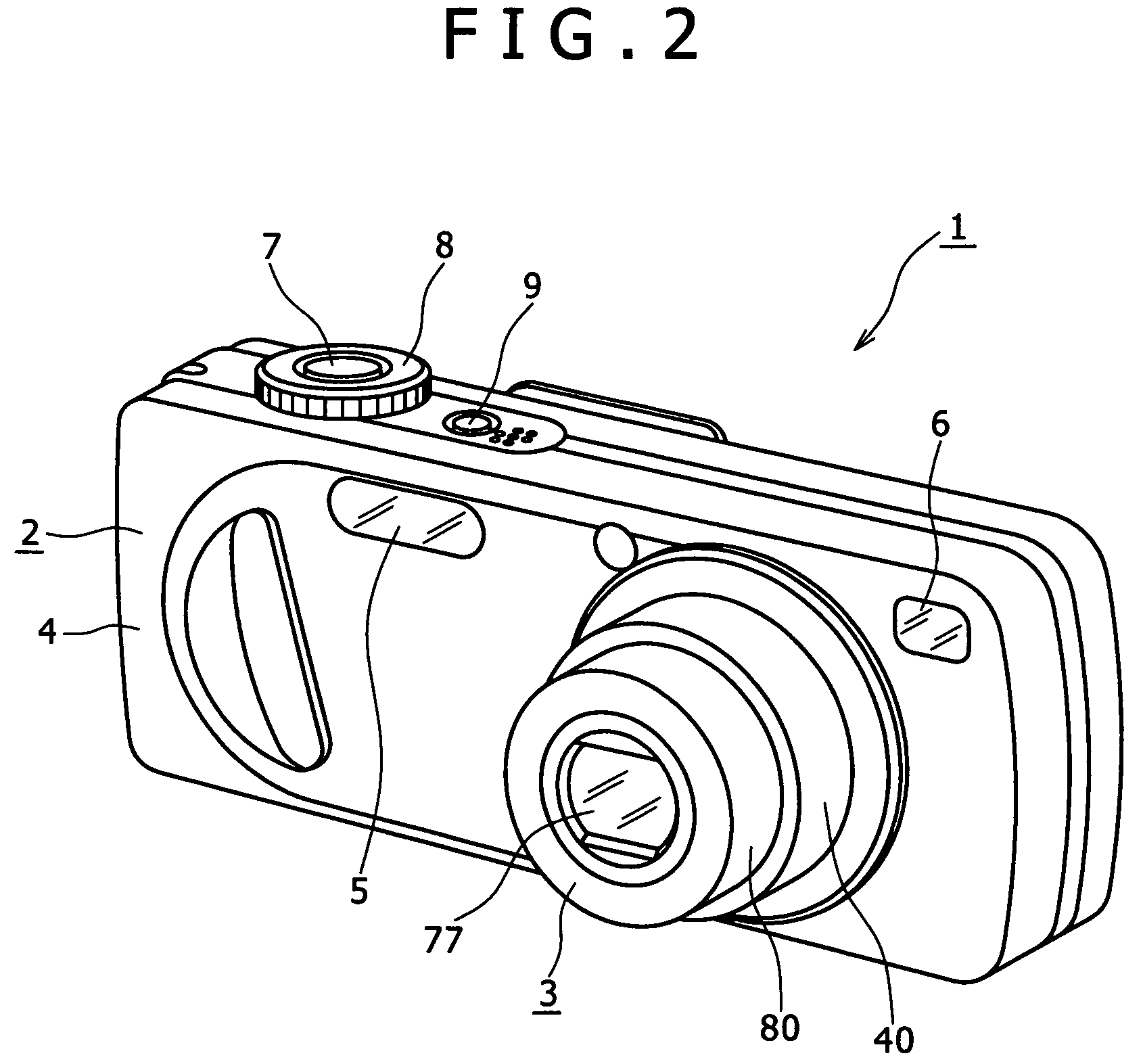
[0037]In the embodiment described below, the present invention is applied to a still camera. It is to be noted that the application of the present invention is not limited to a still camera, but the present invention can be applied widely, for example, to video cameras and various image pickup apparatus incorporated in various other apparatus.

[0038]In the following description, the directions such as forward, backward, upward, downward, leftward and rightward directions are represented as directions as viewed from an image pickup person upon image pickup of the still camera. Accordingly, the image pickup object side is represented as the front side while the image pickup person side is represented as the rear side.

[0039]It is to be noted that the forward, backward, upward, downward, leftward and rightward directions used in the following descript...


PUM

PropertyMeasurementUnit
rotationaaaaaaaaaa
outer circumferenceaaaaaaaaaa
cylindrical shapeaaaaaaaaaa

Abstract

Disclosed herein is a light amount adjustment apparatus, including: a light amount adjustment member; a rotatable magnet formed in a disk shape; a driving arm configured to be pivoted by rotation of the magnet to operate the light amount adjustment member; a core having a pair of confronting portions positioned so as to sandwich the magnet from an outer circumference side and a connecting portion configured to connect end portions of the confronting portions to each other; a coil through which one of the portions of the core extends; and a base member having the core attached to the base member and supporting the magnet for rotation on the base member. The base member has a plurality of attaching projections provided at least at two places of the base member for attaching the core to the base member. The attaching projections have a small projection for fitting with the core.

Description

CROSS REFERENCES TO RELATED APPLICATIONS[0001]The present application claims priority from Japanese Patent Application No. JP 2007-009442 filed in the Japanese Patent Office on Jan. 18, 2007, the entire content of which is incorporated herein by reference.BACKGROUND OF THE INVENTION[0002]1. Field of the Invention[0003]This invention relates to a light amount adjustment apparatus and an image pickup apparatus, and more particular to a light amount adjustment apparatus and an image pickup apparatus wherein a core of an electromagnet is attached to a base member.[0004]2. Description of the Related Art[0005]An image pickup apparatus of a video camera, a still camera or a light apparatus includes a light amount adjustment apparatus for adjusting the amount of light fetched through a lens group.[0006]In one of such light amount adjustment apparatus, shutter blades, a filter blade or the like serving as light amount adjustment members are supported for pivotal motion on a base member. The ...

Claims


Application Information

Patent Timeline
Patent Type & Authority Patents(United States)
IPC IPC(8): G02F1/00H02K37/00G04C13/11H02K1/22
CPCG03B9/02G03B9/00G03B9/10G03B9/14H02K33/16
Inventor OHKUMA, HIDEO
Owner SONY CORP
Learn More