
Capacitance measurement method employing floating gate of semiconductor device

a technology of capacitor and floating gate, which is applied in the direction of semiconductor/solid-state device testing/measurement, instruments, nuclear elements, etc., can solve the problems of parasitic effects of interconnect capacitance evaluation and erroneous measured capacitance, so as to minimize the influence of gate-to-drain overlap capacitan

Inactive Publication Date: 2010-07-06
DONGBU HITEK CO LTD
View PDF3 Cites 2 Cited by
  • Summary
  • Abstract
  • Description
  • Claims
  • Application Information

AI Technical Summary

Benefits of technology

The present invention provides a capacitance measurement method using a floating gate of a semiconductor device that can minimize the influence of gate-to-drain overlap capacitance and improve measurement resolutions of a capacitor to be measured. The method can also analyze a mismatching characteristic between two capacitors based on the standard slopes obtained from a relationship between the slope and the source current.

Problems solved by technology

Presently, evaluation of the interconnect capacitance might take parasitic effects and requires a technique capable of handling complicated test equipment.
However, when employing the source-flower characteristic of the MOSFET, a charge effect at the floating gate node, which is caused by the gate-to-drain overlap capacitance depending on variation in the voltage between the drain and the floating gate node, is not taken into consideration.
Accordingly, a measured capacitance could be erroneous, in that, it has an error caused by the gate-to-drain overlap capacitance.

Method used


Image

  • Capacitance measurement method employing floating gate of semiconductor device
  • Capacitance measurement method employing floating gate of semiconductor device
  • Capacitance measurement method employing floating gate of semiconductor device

Examples


Embodiment Construction

[0029]Hereinafter, embodiments of the present invention will be described in detail with reference to the accompanying drawings so that they can be readily understood by those skilled in the art.

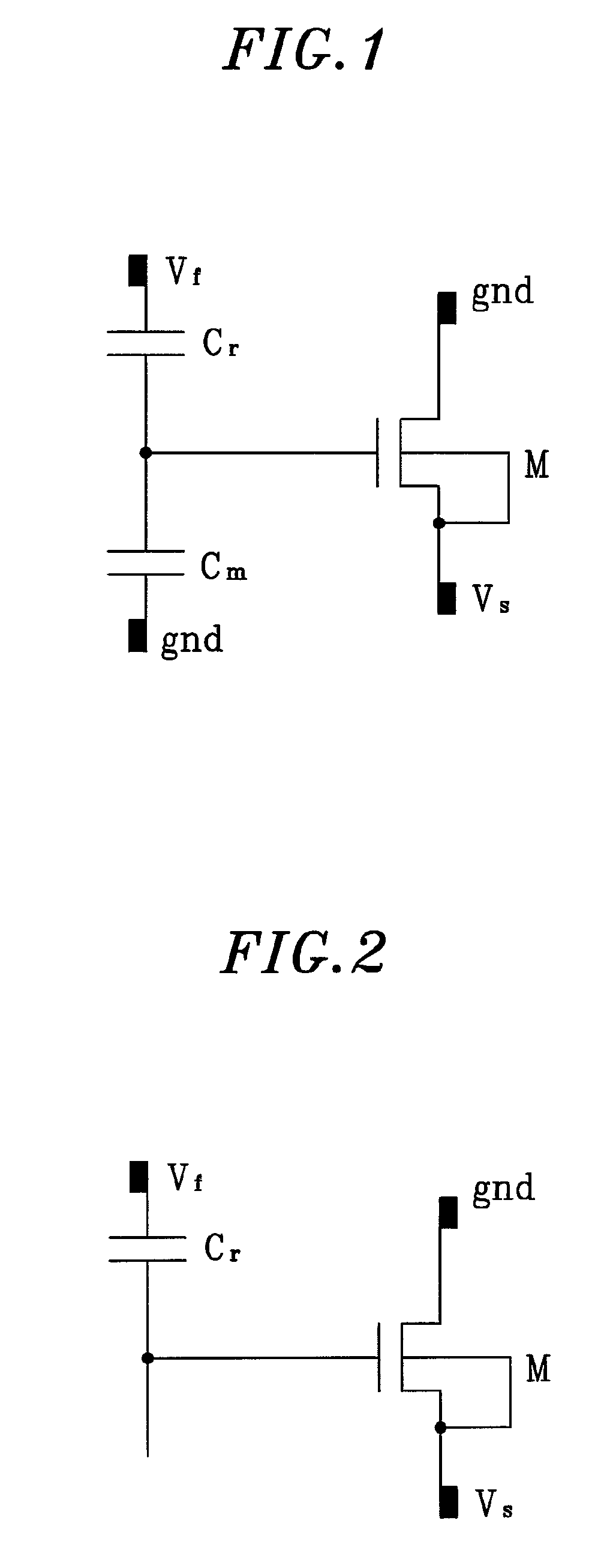
[0030]FIG. 1 is an equivalent circuit diagram of a floating gate structure having a reference capacitance and an unknown capacitance.

[0031]In FIG. 1, even if the voltage Vf applied to the reference capacitor Cr or the voltage applied to the drain or the source of the MOSFET M changes and, if there is no current induced from another node to the floating gate node and the amount of current, which is generated and becomes distinct within the floating gate node is negligible, the floating gate node will be in a neutral condition, that is, at an initial value, a total amount of internal charge is 0. In other words, it is considered that the charge amount of the floating gate node is unchanged. It can be expressed in Equation 2. This condition infers that Vg(t) is constant as time goes by (i.e., V...


PUM


Abstract

A capacitance measurement method employing a floating gate of a semiconductor device in a circuit having a MOSFET in which a drain is connected to a ground and a source and a gate are connected to each other, and a capacitor having a capacitance Cr connected to the gate, includes: obtaining a slope S from a relationship between voltage Vs of the source and a voltage Vf applied to the capacitor; setting a standard slope S0 as a y-intercept of a first-order linear equation obtained from a relationship between the slope S depending on the source current Is and the Vo(Is); and calculating a gate-to-drain overlap capacitance Cdgo of the MOSFET based on a capacitance Cr of the capacitor and the standard slop S0.

Description

FIELD OF THE INVENTION[0001]The present invention relates, in general, to a capacitance measurement method and more particularly, to a capacitance measurement method employing a floating gate of a semiconductor device.BACKGROUND OF THE INVENTION[0002]Presently, evaluation of the interconnect capacitance might take parasitic effects and requires a technique capable of handling complicated test equipment. To the contrary, quasi DC measurement structures provide several methods of evaluating the interconnect capacitance at a narrow test area. A floating gate capacitance measurement method is one of the methods. [C. Kortekaas, “on-chip Quasi-static Floating-gate capacitance Measurement Method”, Proc. IEEE Int. Conf. ON Microelectronic Test Structures, pp. 109-113, Vol 3, March 1990][0003]FIG. 1 is an equivalent circuit diagram of a floating gate structure. The floating gate structure includes one MOSFET M and two first and second capacitors Cr and Cm. The first capacitor Cr is a referen...

Claims


Application Information

Patent Timeline
Patent Type & Authority Patents(United States)
IPC IPC(8): G01R5/28
CPCG01R27/2605H01L27/10H01L22/00H01L21/18
Inventor KIM, JONG MIN
Owner DONGBU HITEK CO LTD
Learn More