
Non-isolated bus converters with voltage divider topology

a voltage divider and converter technology, applied in the direction of dc-dc conversion, power conversion systems, instruments, etc., can solve the problems of insufficient efficiency gains and size reductions achievable from adding buck stages, inability to meet the power requirements of state-of-the-art microprocessors, and inability to provide reliable, small-scale and cost-effective power supplies and power conditioning circuits to meet power requirements. , to achieve the effect of reducing or eliminating the use of filter capacitor

Inactive Publication Date: 2010-06-29
VIRGINIA TECH INTPROP INC
View PDF5 Cites 123 Cited by
  • Summary
  • Abstract
  • Description
  • Claims
  • Application Information

AI Technical Summary

Benefits of technology

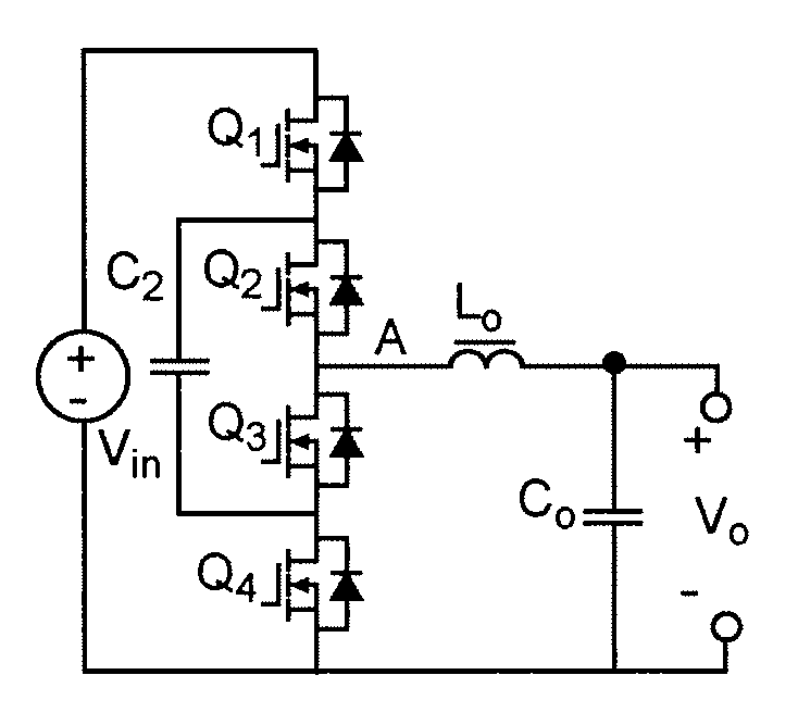
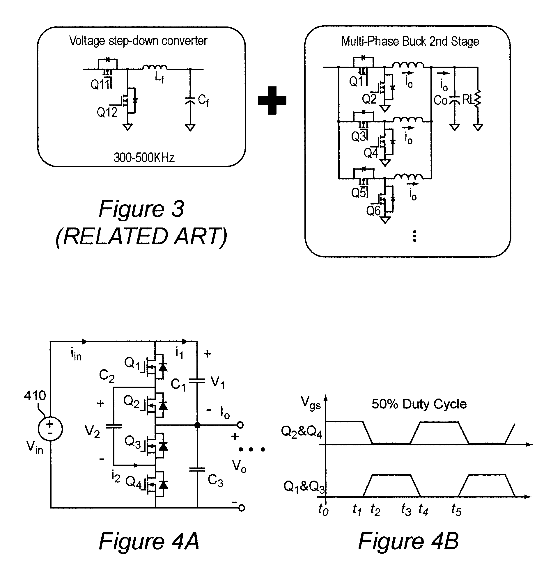
The present invention provides a new way to design power supplies and voltage regulators that reduces or eliminates the use of filter capacitors and increases control bandwidth. This is achieved by using a voltage converter with selective conduction devices connected in series, at least two of which are controllable switches. A capacitor is connected between two of the nodes, and a control arrangement is used to activate the switches in a mutually exclusive manner to create two different conduction paths, each containing the capacitor and the selective conduction devices. This results in the capacitor and the selective conduction devices functioning as a capacitive voltage divider or a voltage multiplier.

Problems solved by technology

Providing reliable, small size, and cost effective power supplies and power conditioning circuits to meet the power requirements of state of the art microprocessors is increasingly difficult.
In fact, present state of the art DC-DC converter circuits and voltage regulators will soon be inadequate for use with many foreseeable microprocessor designs.
Two stage buck converters tend to reduce switching losses and reverse recovery losses in the buck converter switches.
However, the efficiency gains and size reductions achievable from adding buck stages are inherently limited.
Two stage buck converters may not be able to meet the power requirements of microprocessors in a cost effective circuit of acceptably small size.
On the contrary, the rate of change of current that can be delivered to a load, referred to as slew rate, is limited not only by the transient performance of the power supply / voltage regulator (hereinafter sometimes referred to simply as VR or voltage regulator module (VRM)) itself but by interconnect parasitics which can be excessive and further limit transient performance.
Therefore, use of filter capacitors of increasing values and size have been used for energy storage to meet needed slew rates even though the limited control bandwidth of VRs is compromised by such increased capacitance.
However, such an option has not been widely adopted because the efficiency of known voltage converter topologies is significantly reduced when switching frequencies are increased because the major loss factors are switching losses and body conduction losses associated with the inherent diode in MOSFETs which are used for switching.

Method used


Image

  • Non-isolated bus converters with voltage divider topology
  • Non-isolated bus converters with voltage divider topology
  • Non-isolated bus converters with voltage divider topology

Examples


Embodiment Construction

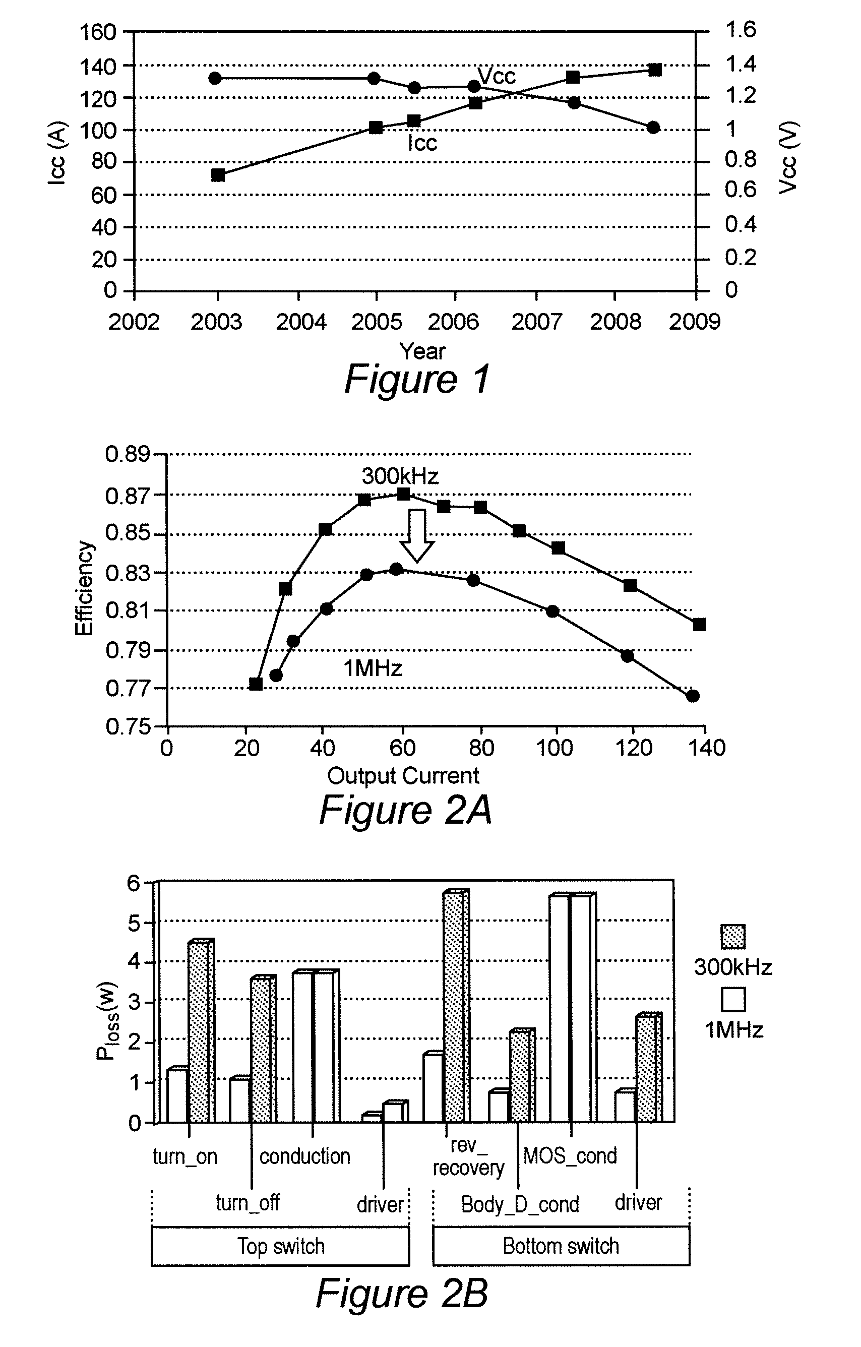
[0026]Referring now to the drawings, and more particularly to FIG. 1, there is shown a graphical depiction of trends in voltage and current requirements for microprocessors as microprocessors have developed, and including projections of voltage and current requirements for foreseeable designs. Basically, since clock cycle times are desirably as short as possible, higher integration density is desirable to reduce signal propagation time which is principally a function of interconnect length and consequent interconnect resistance and capacitance. Reduced interconnect length and capacitance also reduces susceptibility to noise. Therefore, higher integration density is required to minimize interconnect length and capacitance which allows more devices and functions to be provided on a single chip, thus also reducing need for interchip connections in many instances and the number of chips required for a given functionality.

[0027]Increased integration density thus limits the voltage which ...


PUM


Abstract

A voltage converter having four switches Q1, Q2, Q3, Q4, connected in series and operated in pairs in a complementary fashion. An input voltage is provided across the four switches. A middle capacitor is connected in parallel with two middle switches Q2, Q3. Voltage output is provided across switches Q3 and Q4 (i.e. at a midpoint of the four switches). Series-connected output capacitors can be connected in parallel with the set of four switches. The middle capacitor alone or in combination with parallel connected capacitors, when connected to the input voltage or output terminals functions as a capacitive voltage divider for voltage conversion and / or regulation with extremely high efficiency and which can provide either step-down or step-up function. Also, an output inductor can be provided as a perfecting feature to further increase efficiency. Alternatively, two of the four switches can be replaced with rectifying diodes. Alternatively, the voltage converter has two or more sets of four switches connected in parallel. The two sets can be connected by resistor-capacitor ladder, or an inductor-capacitor ladder for charge / voltage sharing to reduce voltage ripple.

Description

[0001]This application claims benefit of priority of the filing date of U.S. Provisional Patent Application 60 / 816,644, filed Jun. 27, 2006, the entirety of which is hereby incorporated by reference as if fully set forth herein.BACKGROUND OF THE INVENTION[0002]1. Field of the Invention[0003]The present invention generally relates to voltage converters and regulators and, more particularly, to voltage converters and regulators having several switches or other devices connected in series to form a voltage divider. The circuits in accordance with the present invention are particularly useful for providing low voltages at high currents needed for modern microprocessors. The non-isolated bus converters are suitable for high power density, high efficiency non-isolated unregulated DC / DC conversion but can be operated to provide good voltage regulation, as well.[0004]2. Description of the Prior Art[0005]As microprocessor technology advances, the required microprocessor power supply must pro...

Claims


Application Information

Patent Timeline
Patent Type & Authority Patents(United States)
IPC IPC(8): G05F1/613G05F1/40
CPCH02M1/14H02M3/1584H02M3/157H02M1/0043H02M7/4837
Inventor XU, MINGSUN, JULULEE, FRED C.
Owner VIRGINIA TECH INTPROP INC
Learn More