
Method and apparatus for preventing head of line blocking in an ethernet system

a technology of ethernet system and head of line, applied in the field of network operation, can solve the problems of degrading the performance of the entire network, blocking the network, and conventional network interfaces not communicating with their attached switches about the status of queues, so as to reduce the bandwidth of traffic flow, reduce the load of ethernet system, and reduce the effect of bandwidth

Active Publication Date: 2010-06-22
MARVELL ISRAEL MISL
View PDF18 Cites 32 Cited by
  • Summary
  • Abstract
  • Description
  • Claims
  • Application Information

AI Technical Summary

Benefits of technology

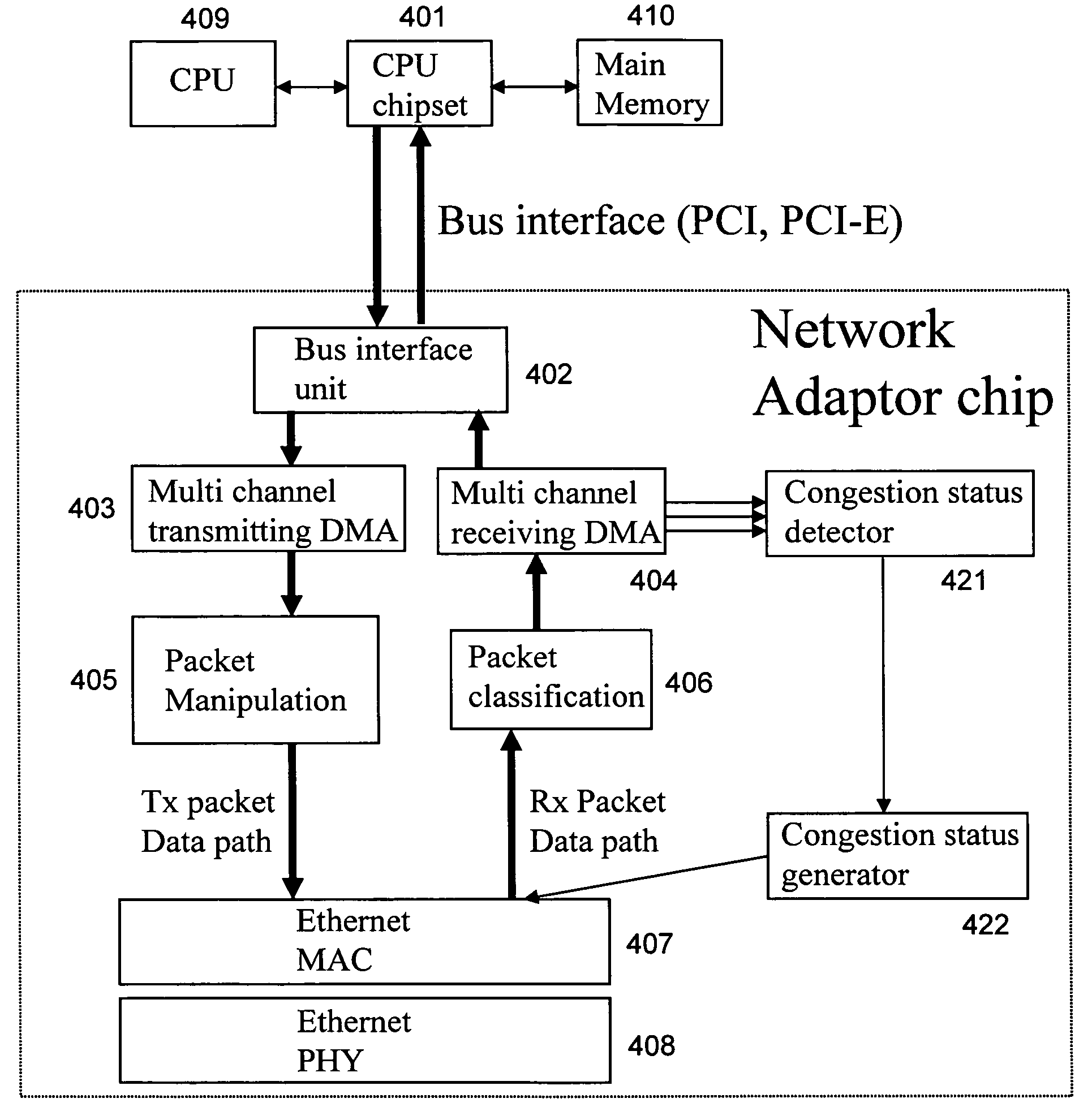
[0016]One object of the present invention is to provide a method for preventing head of line blocking in an Ethernet system, using Ethernet protocol and media to communicate congestion information. In one embodiment, a network interface detects whether there is traffic flow congestion between the network interface and a data processing unit to which the network interface is connected, such as a CPU on the line card, a CPU connected to the line card, or a peripheral. If yes, the network interface communicates the congestion status to its attached Ethernet switch. The Ethernet switch then stops serving the congested port or queue.
[0018]Another object of the present invention is to provide an Ethernet network interface, which can detect traffic flow congestion between the network interface and a data processing unit to which the network interface is connected, such as a CPU on the line card, a CPU connected to the line card, or a peripheral, and communicates the congestion status to its attached switch.
[0020]A further object of the present invention is to provide an Ethernet system, comprising a network interface which can detect traffic flow congestion between the / network interface and a data processing unit to which the network interface is connected, such as a CPU on the line card, a CPU connected to the line card, or other peripheral, and communicates the congestion status to its attached switch; and an Ethernet switch which can reduce bandwidth for traffic flow causing the congestion when receiving the congestion status from a network interface.

Problems solved by technology

However, that flow control causes blocking in the network.
As a result, the slowest link would degrade the performance of the entire network.
However, conventional network interfaces do not communicate with their attached switches about queue status of the network interfaces.
The only such known mechanism is the disadvantageous 802.3x flow control mechanism.

Method used


Image

  • Method and apparatus for preventing head of line blocking in an ethernet system
  • Method and apparatus for preventing head of line blocking in an ethernet system
  • Method and apparatus for preventing head of line blocking in an ethernet system

Examples


Embodiment Construction

[0027]Embodiments of the present invention are described herein with reference to the accompanying drawings, similar reference numbers being used to indicate functionally similar elements.

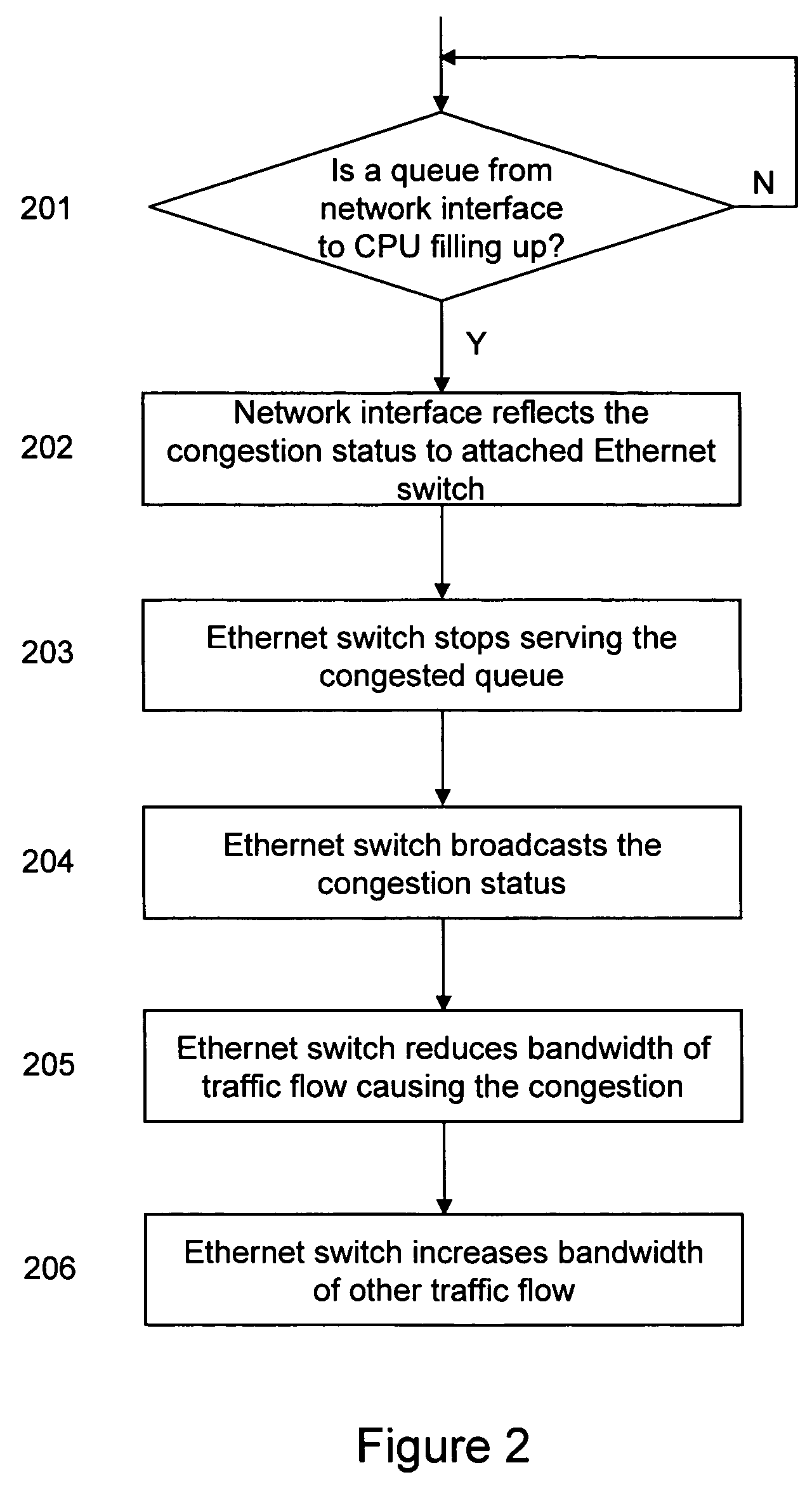
[0028]FIG. 2 shows a flow chart for traffic flow control in an Ethernet system according to one embodiment of the present invention. In one embodiment of the present invention, the line card is a server blade, which has one or more CPU subsystems running application software, and communicating with other line cards using Ethernet. It should be understood that the network interface of the present invention is not limited to an adapter between user equipment and the Ethernet, but could be any interface between a packet destination and the Ethernet.

[0029]At step 201 in FIG. 2, the network interface 1054 detects that one or more of its queues, for example, its DMA queues to the CPU memory, start to fill up. At step 202, the network interface 1054 informs its attached switch, the switch 1051, about the ...


PUM


Abstract

A method for preventing head of line blocking in an Ethernet system. In one embodiment, a network interface detects whether there is traffic flow congestion between the network interface and a data processing unit such as a CPU or other peripheral. If yes, the network interface communicates the congestion status to its attached Ethernet switch. In another aspect of the invention, the Ethernet switch then stops serving the congested port or queue, and informs a switch from which the traffic flow causing the congestion originates. In a further aspect, the originating switch then reduces bandwidth for the traffic flow causing the congestion. In a still further aspect, the originating switch can take the bandwidth that it acquired because of reducing the congesting traffic flow, and use it to increase bandwidth for other traffic flow.

Description

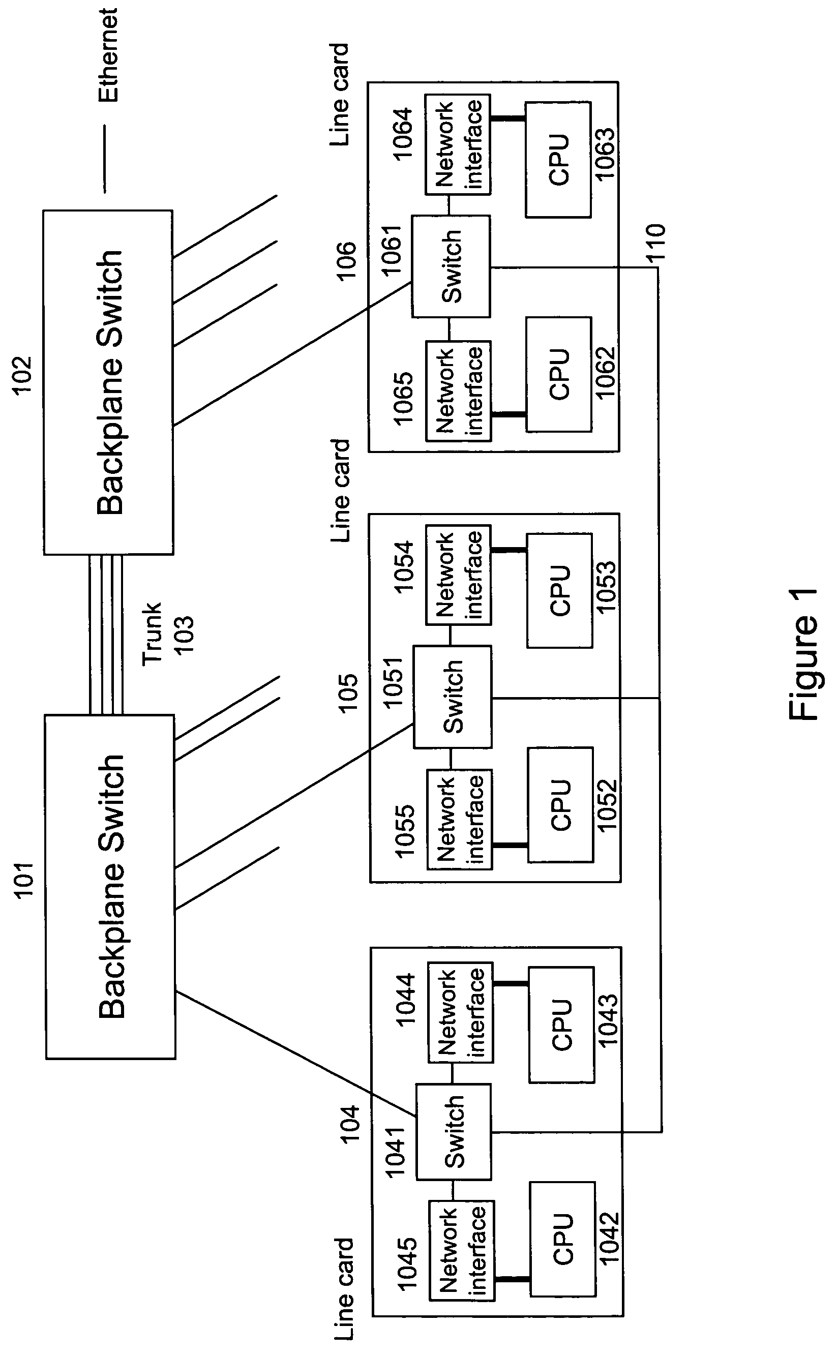
CROSS-REFERENCE TO RELATED APPLICATIONS[0001]This application incorporates by reference a patent application filed on the same day as the present application, Ser. No. 10 / 955,893 and entitled Method and Apparatus for Preventing Head of Line Blocking among Ethernet Switches.FIELD OF THE INVENTION[0002]The present invention relates to networking, and more specifically to traffic flow control in Ethernet networks.BACKGROUND OF THE INVENTION[0003]FIG. 1 shows a block diagram of a conventional Ethernet switching system. As shown, the Ethernet system comprises backplane switches 101 and 102, communicating with each other via a trunk line 103. The Ethernet system also comprises a plurality of line cards, including line cards 104, 105, and 106. Each of the line cards includes a switch, such as a switch 1041 in the line card 104, a switch 1051 in the line card 105, and a switch 1061 in the line card 106. Each of the switches communicates with a backplane switch (either of backplane switches ...

Claims


Application Information

Patent Timeline
Patent Type & Authority Patents(United States)
IPC IPC(8): H04L12/26
CPCH04L47/11H04L47/13H04L47/266H04L49/351H04L47/30H04L43/0882Y02B60/31H04L49/254H04L49/503Y02D30/50H04L47/2433
Inventor MEDINA, EITAN
Owner MARVELL ISRAEL MISL
Learn More