Method for operating an internal combustion engine

a technology of internal combustion engine and combustion chamber, which is applied in the direction of machines/engines, electrical control, mechanical equipment, etc., can solve the problems of deterioration of the induction of fresh combustion air or fresh mixture, reducing the efficiency of combustion, and increasing the rpm at the first. , to achieve the effect of increasing the rpm

Active Publication Date: 2010-06-15
ANDREAS STIHL AG & CO KG
View PDF6 Cites 4 Cited by
  • Summary
  • Abstract
  • Description
  • Claims
  • Application Information

AI Technical Summary

Benefits of technology

[0007]It is an object of the invention to provide a method for operating an internal combustion engine wherein an uncontrolled large increase of the rpm from the full load rpm is avoided.
[0010]To avoid the excessive increase of rpm, the internal combustion engine is so controlled in a high rpm range above the rated rpm and below the rpm in the regulating range that the number of combustions is less than the number of engine cycles in the same time interval. The rated rpm is the rpm of the engine at maximum power. It has been shown that by controlling the engine so that the number of combustions is less than the number of engine cycles in the same time interval, the tendency to self ignition can be considerably reduced above the full load rpm. If a combustion takes place for each revolution of the crankshaft, then the occurring combustion is comparatively weak because exhaust gases from the previous engine cycle can still be present in the combustion chamber. Because the engine is so controlled that a combustion does not take place for each engine cycle, the occurring combustions are very intense. If the internal combustion engine is a two-stroke engine, then the very intense combustion in the combustion chamber effects a pressure increase in the crankcase via the transfer channels of the two-stroke engine. This pressure increase effects that, in the following engine cycle, the induction of fresh combustion air or fresh mixture is deteriorated. For the following engine cycle, no mixture quantity is present in the combustion chamber which is sufficient for a self ignition. Because no combustion takes place in this engine cycle, pressure and temperature in the combustion chamber can continue to decrease so that the probability of a self ignition is reduced also for the follow-on combustions. The control of the internal combustion engine in such a manner that the number of combustions is less than the number of engine cycles in the same time interval causes that no self ignitions can occur in the high rpm range.
[0011]The same applies when the internal combustion engine is a four-stroke engine. In this case, an engine cycle includes two revolutions of the crankshaft whereas an engine cycle in a two-stroke engine includes one revolution of the crankshaft. For a four-stroke engine, it is achieved that via a very good combustion in the high rpm range, the pressure level in the combustion chamber is increased in the subsequent induction cycle so that no mixture quantity, which is sufficient for a self ignition, can be inducted. In the follow-on engine cycles, pressure and temperature have decreased so far that the probability of self ignition is significantly reduced. Self ignitions can in this way be effectively prevented also for a four-stroke engine.
[0012]Because the formation of self ignitions is prevented in the high rpm range, the rpm of the internal combustion engine can be reduced in the regulating range in the usual manner, for example, by interrupting the ignition. An uncontrolled large increase of the rpm can be avoided in that the engine is so controlled in an rpm range below the regulating range that the number of combustions is less than the number of engine cycles in the same time interval.
[0013]It has been shown that the formation of self ignitions can be effectively prevented when the engine is so controlled that in the high rpm range at most nine combustions take place for ten engine cycles. Already by preventing individual combustions, for example, by interrupting the ignition, self ignitions can be avoided. It is advantageous to suppress every seventh combustion by corresponding control of the internal combustion engine. It can, however, also be provided that the internal combustion engine is so controlled that a lower number of combustions takes place. Especially, the internal combustion engine is so controlled that, in the high rpm range, a combustion takes place at most every four engine cycles. Advantageously, the internal combustion engine is so controlled that, in the high rpm range, the number of combustions is at a ratio of 1 to 4 to 1 to 10 to the number of engine cycles. Because the combustion chamber is scavenged over three to nine engine cycles after a combustion takes place, it is ensured that also the next combustion is very good and leads to a very high pressure in the combustion chamber which prevents an adequate induction of mixture for a self ignition in the next engine cycle.

Problems solved by technology

The interruption of the ignition has, however, no effect for revolutions wherein the mixture ignites automatically so that the rpm at first greatly increases when the load drops away.
If a combustion takes place for each revolution of the crankshaft, then the occurring combustion is comparatively weak because exhaust gases from the previous engine cycle can still be present in the combustion chamber.
This pressure increase effects that, in the following engine cycle, the induction of fresh combustion air or fresh mixture is deteriorated.

Method used


Image

  • Method for operating an internal combustion engine
  • Method for operating an internal combustion engine
  • Method for operating an internal combustion engine

Examples


Embodiment Construction

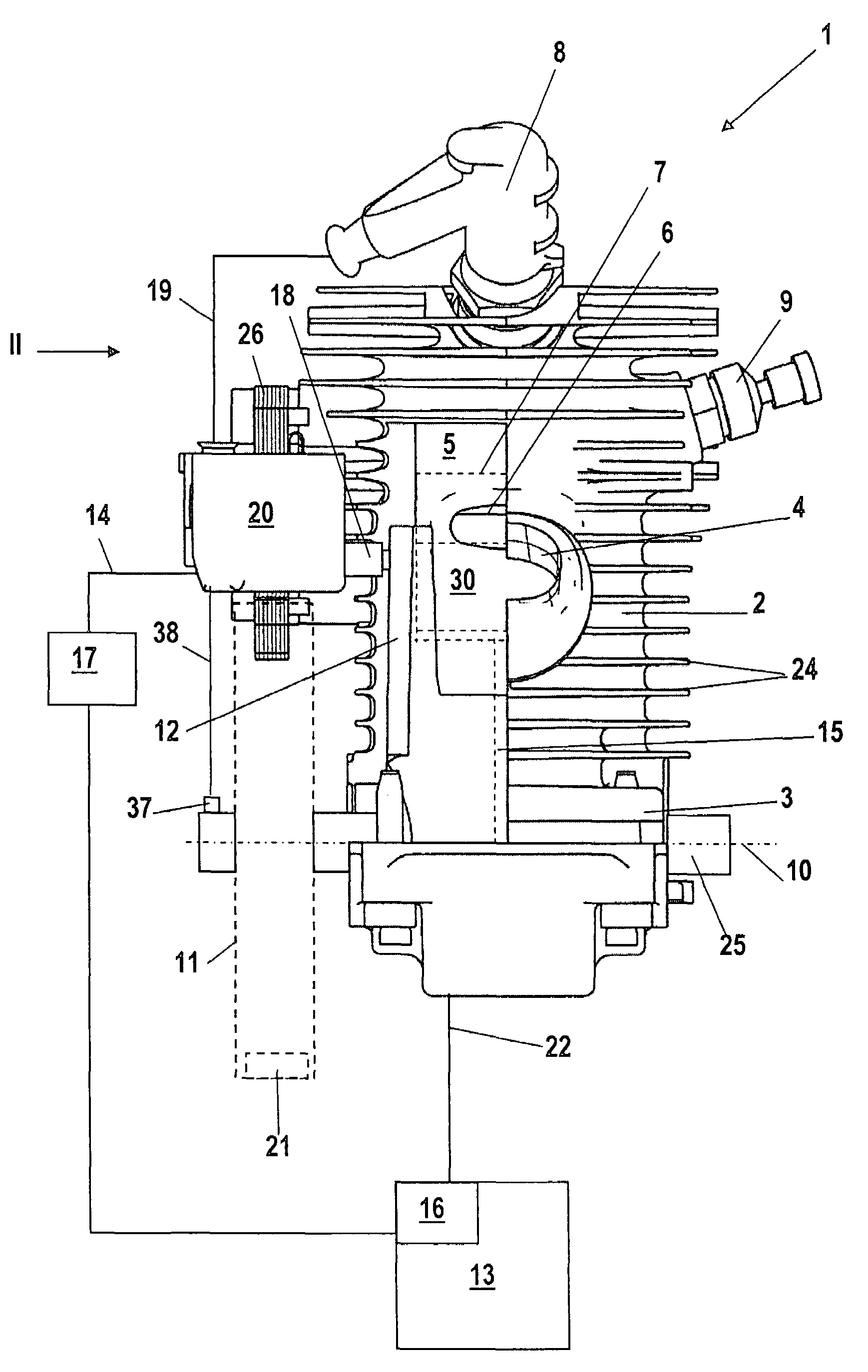
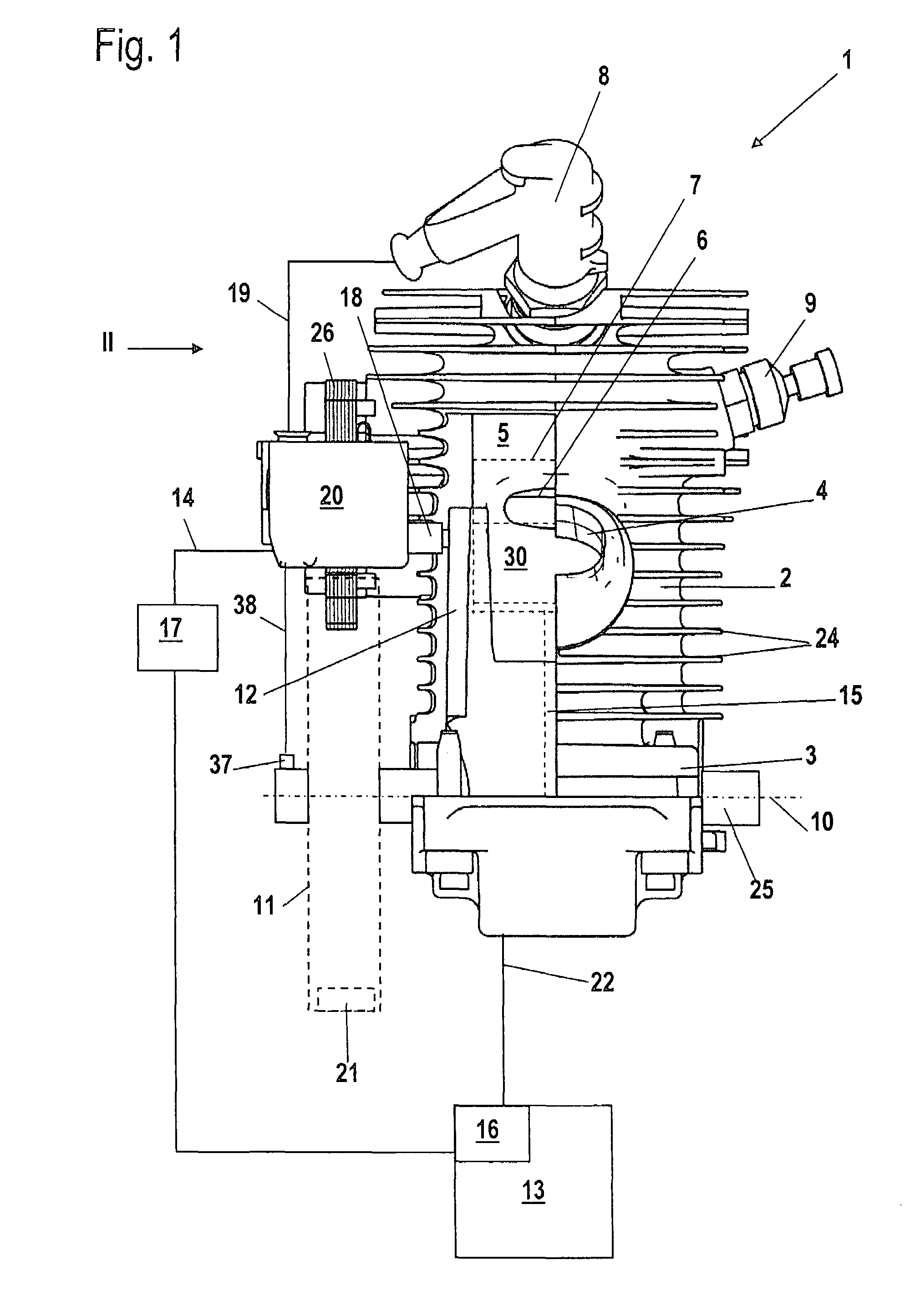
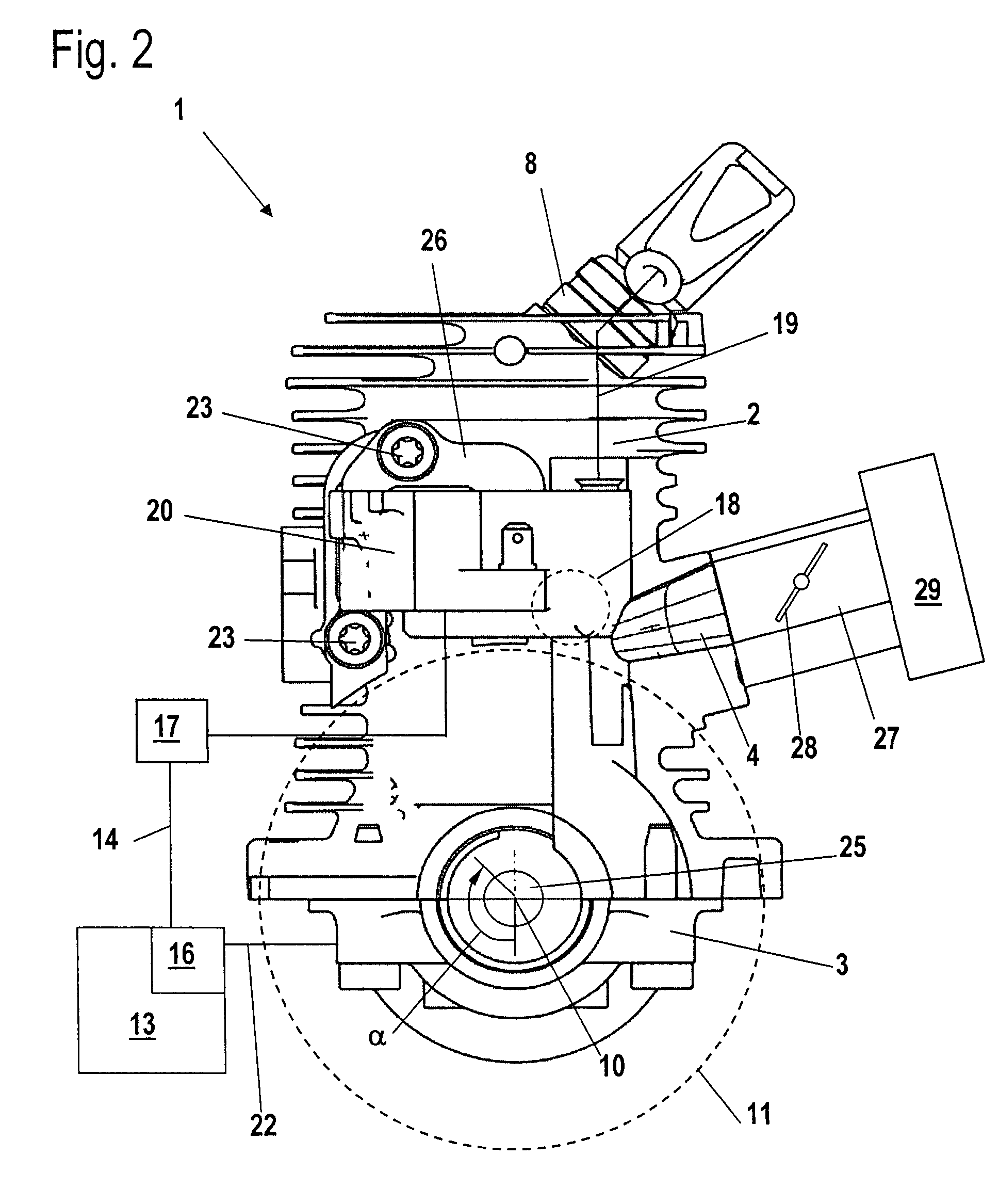
[0028]The internal combustion engine shown in FIG. 1 is configured as a two-stroke engine. The two-stroke engine 1 has a cylinder 2 having cooling ribs 24 arranged on the outer surface thereof. A piston 7 is reciprocally journalled in the cylinder 2 and is shown in phantom outline. The piston 7 drives a crankshaft 25 via a connecting rod 15. The crankshaft 25 is rotatably journalled in a crankcase 3 about the crankshaft axis 10. An inlet 4 opens on the cylinder 2 via which substantially fuel-free combustion air is supplied to the two-stroke engine which is configured as a single cylinder engine.

[0029]The two-stroke engine 1 includes at least one transfer channel 12 which connects the crankcase 3 to a combustion chamber 5 in the region of bottom dead center of the piston 7. The combustion chamber 5 is delimited by the cylinder 2 and the piston 7. Two or four transfer channels 12 are provided and are arranged symmetrically with respect to a partitioning center plane centered with resp...


PUM


Abstract

An internal combustion engine includes a cylinder (2) wherein a combustion chamber (5) is formed. The engine also includes devices for metering fuel and combustion air as well as an ignition device for igniting the mixture in the combustion chamber (5). A method for operating the internal combustion engine provides that fuel and combustion air are supplied to the engine and the mixture is ignited in the combustion chamber (5). The combustion chamber (5) is delimited by a piston (7) which drives a crankshaft (25) rotatably journalled in a crankcase (3). A control is provided which controls the supply of fuel and the ignition of the mixture in the combustion chamber (5). The internal combustion engine is so controlled in at least one operating state that the number of combustions is less than the number of engine cycles in the same time span. To avoid the formation of self ignitions, the operating state is a high rpm range wherein the rpm lies above the rated rpm and below the rpm in a regulating range.

Description

CROSS REFERENCE TO RELATED APPLICATIONS[0001]This application claims priority of German patent application no. 10 2006 032 474.9, filed Jul. 13, 2006, the entire content of which is incorporated herein by reference.BACKGROUND OF THE INVENTION[0002]A method of the above kind for operating an internal combustion engine is disclosed in United States patent application publication no. US 2006 / 0157006 A1 (now U.S. Pat. No. 7,325,528) which is incorporated herein by reference and is assigned to the same assignee as the present application.[0003]U.S. Pat. No. 5,901,673 discloses a two-stroke engine wherein fuel is injected into the combustion chamber for each crankshaft revolution in the region of bottom dead center of the piston and the air / fuel mixture, which is formed in the combustion chamber, is ignited in the region of the top dead center of the piston.[0004]United States patent application publication no. US 2006 / 0157006 A1 (now U.S. Pat. No. 7,325,528) discloses controlling a two-s...

Claims


Application Information

Patent Timeline
Patent Type & Authority Patents(United States)
IPC IPC(8): F02B75/02F02P5/00
CPCF02D41/3058F02P9/005F02D41/0087F02D2400/04F02D2400/06
Inventor KUNERT, NILSBORCHARDT, JANBAHNER, ANDREASOSTOJIC, PREDAGLINGEN, ANDREAS
Owner ANDREAS STIHL AG & CO KG
Why Eureka
Try Eureka