Magnetic field coil and magnetic resonance imaging apparatus
a magnetic field coil and magnetic resonance imaging technology, applied in the field of magnetic field coils, can solve the problems of insufficient sensitivity and limited region providing favorable sensitivities for both kinds of signals, and achieve high sensitivity, uniform sensitivity, and high sensitivity.
- Summary
- Abstract
- Description
- Claims
- Application Information
AI Technical Summary
Benefits of technology
Problems solved by technology
Method used
Image
Examples
first embodiment
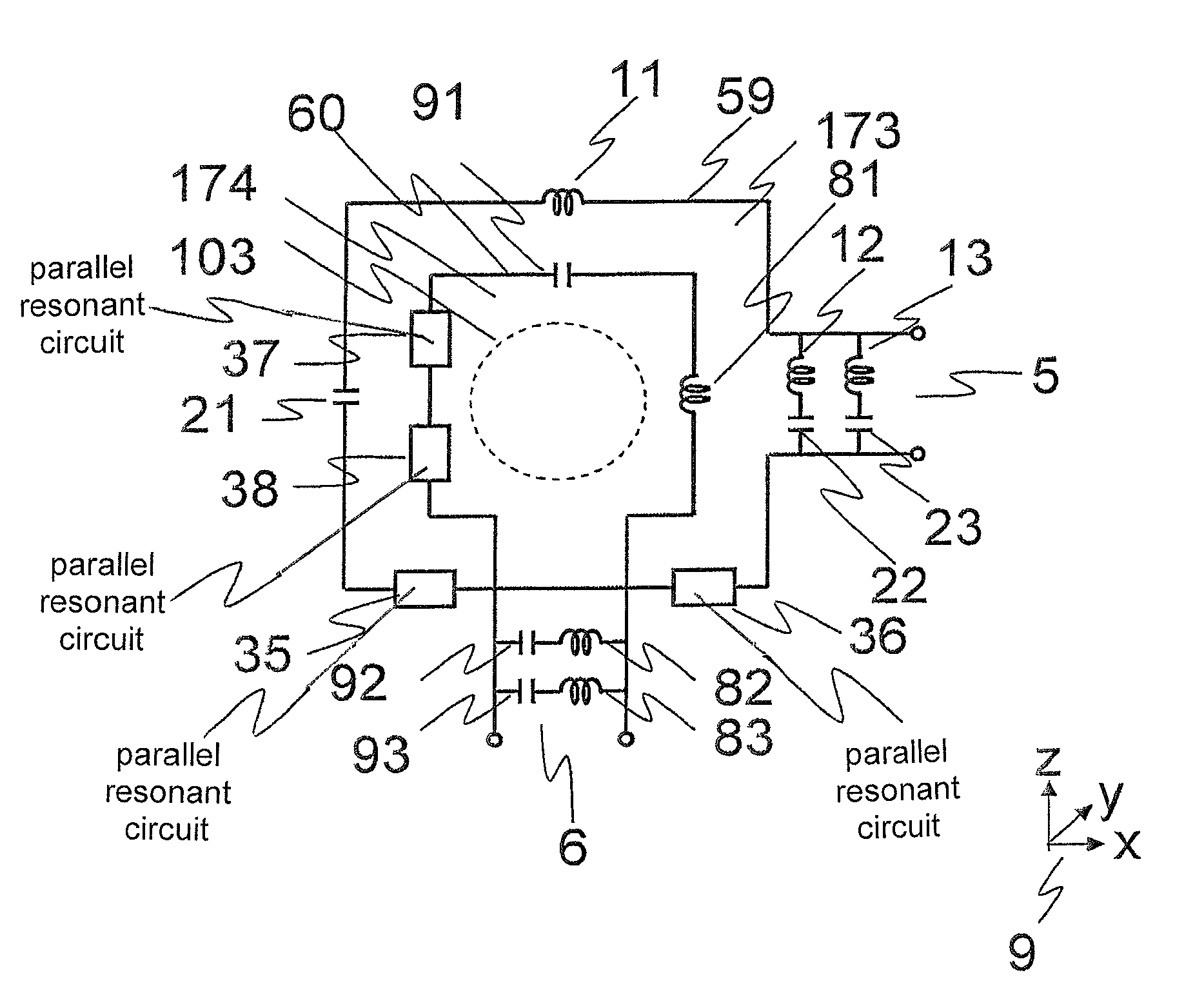
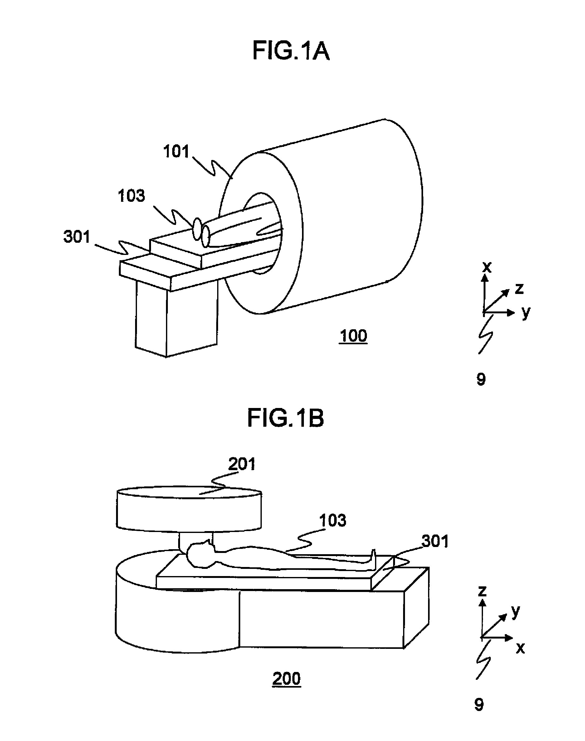
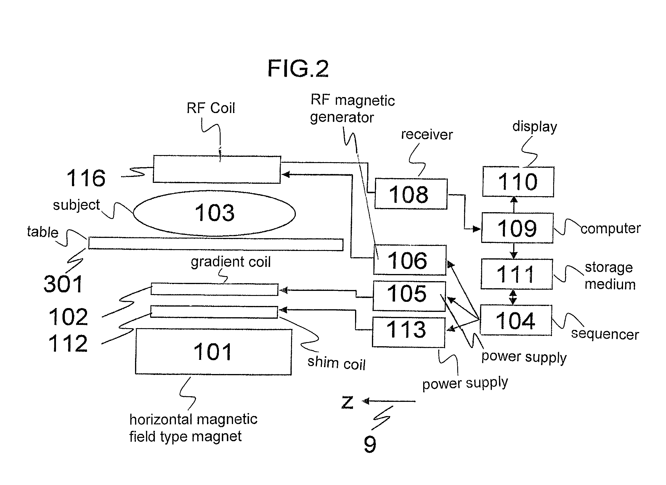
[0033]The first embodiment of the RF coil according to the present invention will be explained. The whole configuration of an MRI apparatus having the RF coil of this embodiment will be explained first. FIG. 1A and FIG. 1B are schematic views of the MRI apparatus having the RF coil of this embodiment. In the diagrams, the direction of the z axis in the coordinate 9 is a static magnetic field direction. The MRI apparatus 100 shown in FIG. 1A is provided with a horizontal magnetic field type magnet 101. The MRI apparatus 200 shown in FIG. 1B is provided with a vertical magnetic field type magnet 201. These MRI apparatuses 100 and 200 are provided with a table 301 on which a subject 103 is placed. This embodiment is applicable to both the MRI apparatus 100 provided with the horizontal magnetic field type magnet 101, and the MRI apparatus 200 provided with the vertical magnetic field type magnet 201. Hereafter, the present invention will be explained for the MRI apparatus 100 having the...
second embodiment
[0112]Hereafter, the second embodiment of the present invention will be explained. The configuration of the MRI apparatus based on this embodiment is basically the same as that of the first embodiment. In this embodiment, as the transmit and receive RF coil 116, a combination of two of double-tuned loop-type coils 150 of the first embodiment is used to realize the quadrature detection (QD) for improving irradiation efficiency and reception sensitivity of the transmit and receive RF coil. The configuration of this embodiment different from that of the first embodiment will be explained below.
[0113]FIG. 12A and FIG. 12B are diagrams for explaining the transmit and receive RF coil 116 of this embodiment, and FIG. 12A is a circuit diagram of the transmit and receive RF coil 116. In the diagram, the direction of the z axis in the coordinate 9 is the static magnetic field direction. As shown in this diagram, the transmit and receive RF coil 116 of this embodiment is provided with a first ...
third embodiment
[0121]Hereafter, the third embodiment of the present invention will be explained. The configuration of the MRI apparatus of this embodiment is basically the same as that of the first embodiment. In this embodiment, a transmit RF coil 116a and a receive RF coil 116b are independently provided instead of the transmit and receive RF coil 116 of the first embodiment. Here, explanation will be made by exemplifying a case where a double-tuned birdcage RF coil having a birdcage shape is used as the transmit RF coil 116a, and a double-tuned loop-type coil having a loop coil shape is used for the receive RF coil 116b. Hereafter, the embodiment will be explained by emphasizing the configuration different from that of the first embodiment.
[0122]FIG. 14 is a block diagram for explaining connection of the RF coil of this embodiment, a RF magnetic field generator 106 and a receiver 108. As shown in this diagram, the RF coil of this embodiment is provided with a double-tuned birdcage RF coil 70, w...
PUM
 Abstract
Description
Claims
Application Information
 - R&D
- Intellectual Property
- Life Sciences
- Materials
- Tech Scout
- Unparalleled Data Quality
- Higher Quality Content
- 60% Fewer Hallucinations
Browse by: Latest US Patents, China's latest patents, Technical Efficacy Thesaurus, Application Domain, Technology Topic, Popular Technical Reports.
© 2025 PatSnap. All rights reserved.Legal|Privacy policy|Modern Slavery Act Transparency Statement|Sitemap|About US| Contact US: help@patsnap.com


