Carbon nanotube assembly and manufacturing method thereof
a carbon nanotube and assembly technology, applied in the field of carbon nanotube assembly, can solve the problems of difficult selective extraction of only a specific carbon nanotube from the mixture, and the mixing of carbon nanotubes having various structures, so as to facilitate the use of various types of devices, improve the various kinds of physical properties, and facilitate the effect of us
- Summary
- Abstract
- Description
- Claims
- Application Information
AI Technical Summary
Benefits of technology
Problems solved by technology
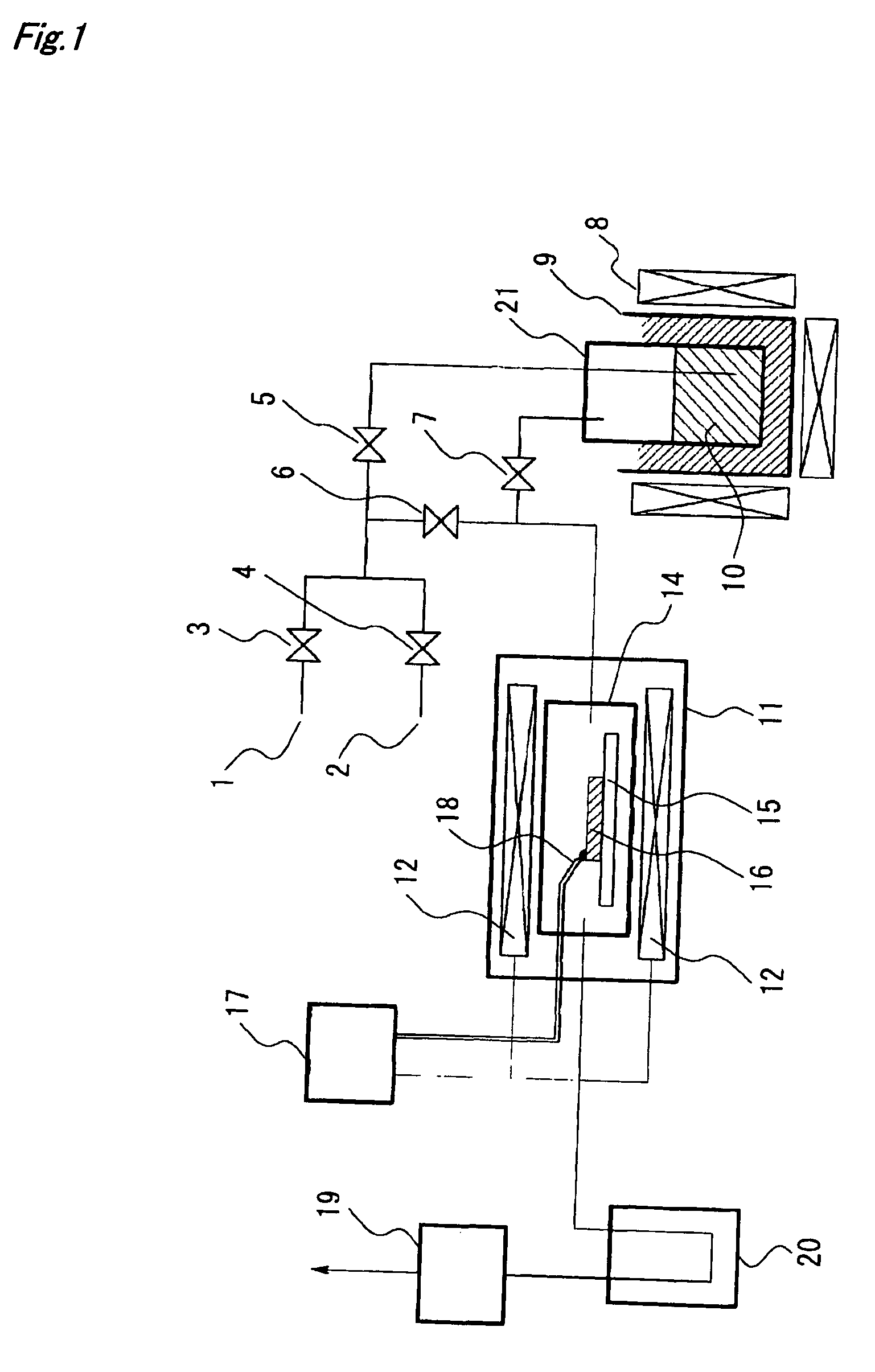
Method used
Image

Examples
example 1
[0160]In Example 1, a substrate of silica glass was used to manufacture single-walled carbon nanotubes using cobalt-molybdenum as a catalyst.
[0161]First, an ethanol solution containing cobalt-molybdenum was prepared. A predetermined amount of cobalt acetate-4 hydrate (purity of 99% or more) and that of molybdenum acetate (dimer, purity of 99% or more) were weighted and dissolved in ethanol (purity of 99.5% or more), whereby a solution having a cobalt concentration of 0.01 mass % and a molybdenum concentration of 0.01 mass % was prepared. Additionally, the cobalt and molybdenum concentrations are metal reduced values.
[0162]Next, two types of silica glass substrates with optically polished surfaces of 20 mm×20 mm×0.5 mm and φ 30 mm×3 mm were prepared and dipped in the cobalt-molybdenum solution for 10 seconds, and thereafter were withdrawn at a rate of 8 mm / sec. The withdrawing was carried out in the atmosphere. The substrate withdrawn from the solution was heated in the atmosphere, w...
example 2
[0176]In Example 2, a carbon nanotube assembly was manufactured on a substrate of silica glass using cobalt-molybdenum fine particles as a catalyst in the same way as Example 1 except using a solution having cobalt of 0.02 mass % and molybdenum of 0.02 mass % for forming the cobalt-molybdenum fine particles.
[0177]As a result of evaluating the number of graphene sheet layers of the carbon nanotubes manufactured in this Example, all of 100 carbon nanotubes extracted at random in total were single-walled carbon nanotubes (SWCNTs: 100%) as illustrated in FIG. 18.
example 3
[0178]In Example 3, a carbon nanotube assembly was manufactured on a substrate of silica glass using cobalt-molybdenum fine particles as a catalyst in the same way as Example 1 except using a solution having cobalt of 0.03 mass % and molybdenum of 0.03 mass % for forming the cobalt-molybdenum fine particles.
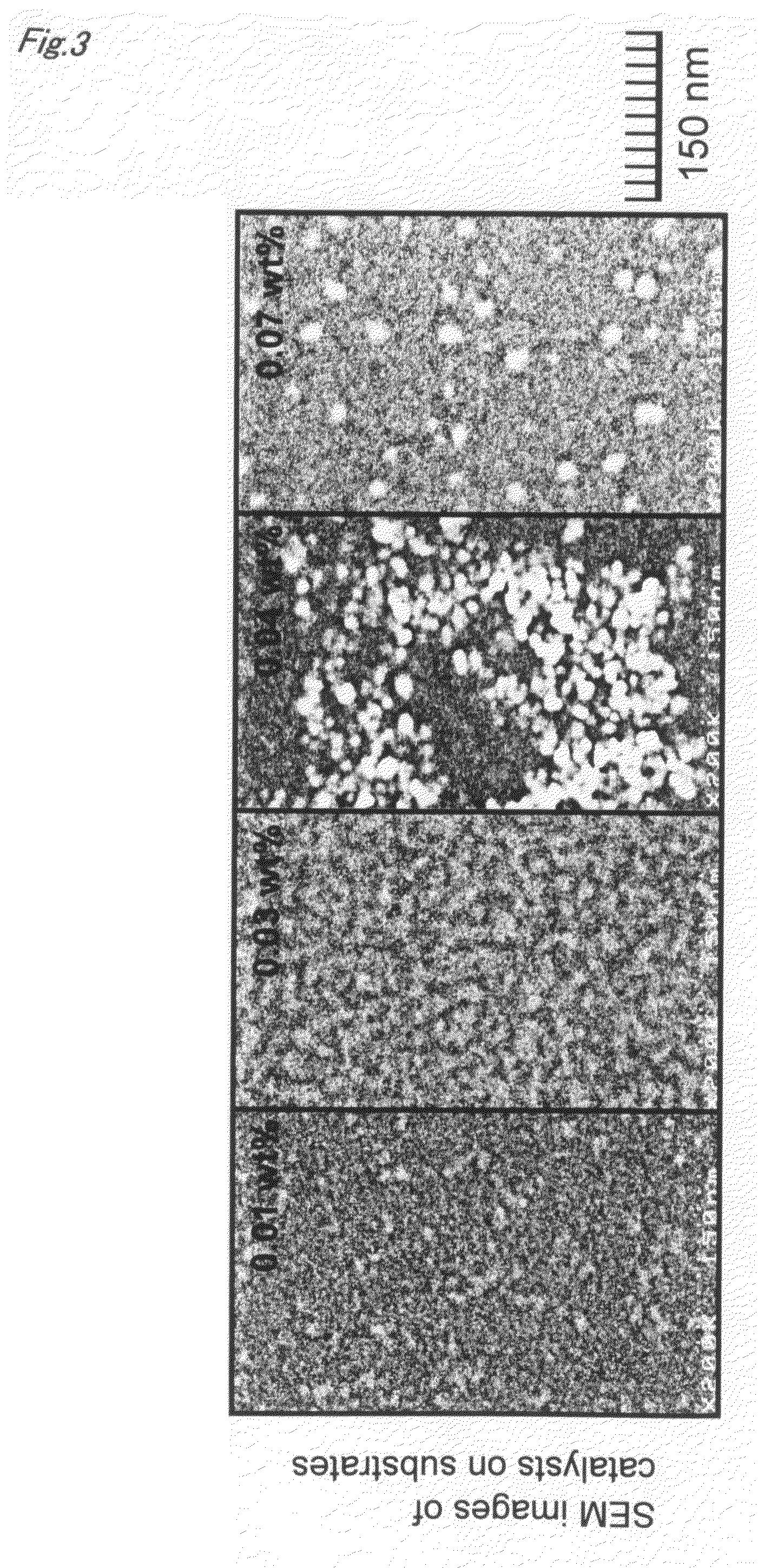
[0179]Moreover, by a high resolution SEM, observation was made of the metallic fine particles just before the growth of carbon nanotubes started in this Example, similar to Example 1. FIG. 3 shows an SEM image of the metallic fine particles on the substrate obtained in Example 3. In connection with each of the reduced metallic fine particles seen in white color in SEM images shown in FIG. 3, the particle diameter was measured using a ruler. As a result, it was recognized that a particle diameter distribution (range of catalyst diameter: 6.1 to 12.0 nm, mean value: 9.4 nm, and standard deviation: 1.32) shown in FIG. 4 was given.
[0180]FIG. 22 is a Scanning Electron Microscope (here...
PUM
| Property | Measurement | Unit |
|---|---|---|
| diameter | aaaaa | aaaaa |
| diameter | aaaaa | aaaaa |
| diameter | aaaaa | aaaaa |
Abstract
Description
Claims
Application Information
 - R&D
- Intellectual Property
- Life Sciences
- Materials
- Tech Scout
- Unparalleled Data Quality
- Higher Quality Content
- 60% Fewer Hallucinations
Browse by: Latest US Patents, China's latest patents, Technical Efficacy Thesaurus, Application Domain, Technology Topic, Popular Technical Reports.
© 2025 PatSnap. All rights reserved.Legal|Privacy policy|Modern Slavery Act Transparency Statement|Sitemap|About US| Contact US: help@patsnap.com