
Split crimper for heat sealing packaging material

Active Publication Date: 2010-06-08
LAKO TOOL & MFG
View PDF40 Cites 52 Cited by
  • Summary
  • Abstract
  • Description
  • Claims
  • Application Information

AI Technical Summary

Benefits of technology

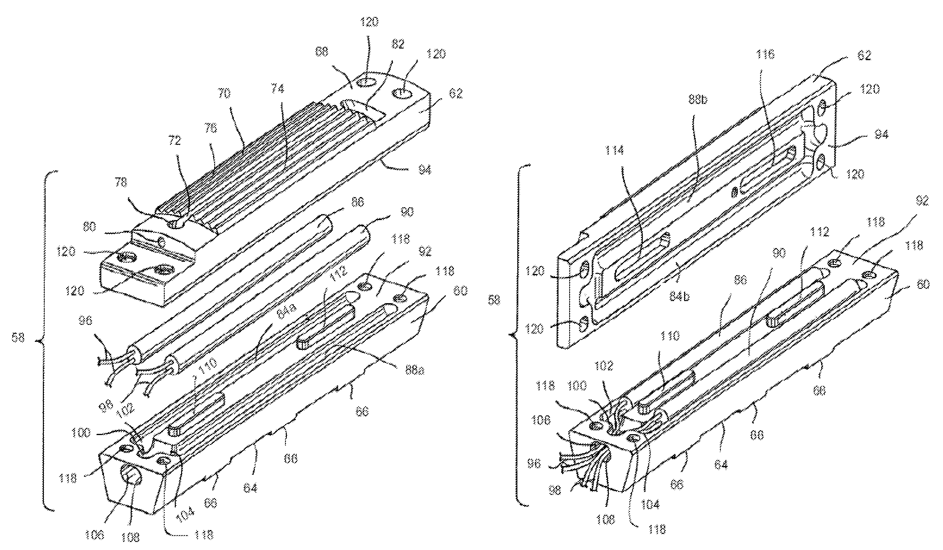
[0009]This invention relates to an improved structure for a split crimper that is adapted for use in a crimping assembly for engaging and heat sealing overlapping layers of a packaging material. The crimper includes a first crimper portion having a crimping su

Problems solved by technology

If an insufficient amount of force is exerted by the crimpers, then the overlapping portions of the sheet of packaging material will not be compressed sufficiently to form a complete seal.
If an excessive amount of force is exerted by the crimpers, the sheet of packaging material will tear or break.
As a result, the set-up is a very time consuming operation.
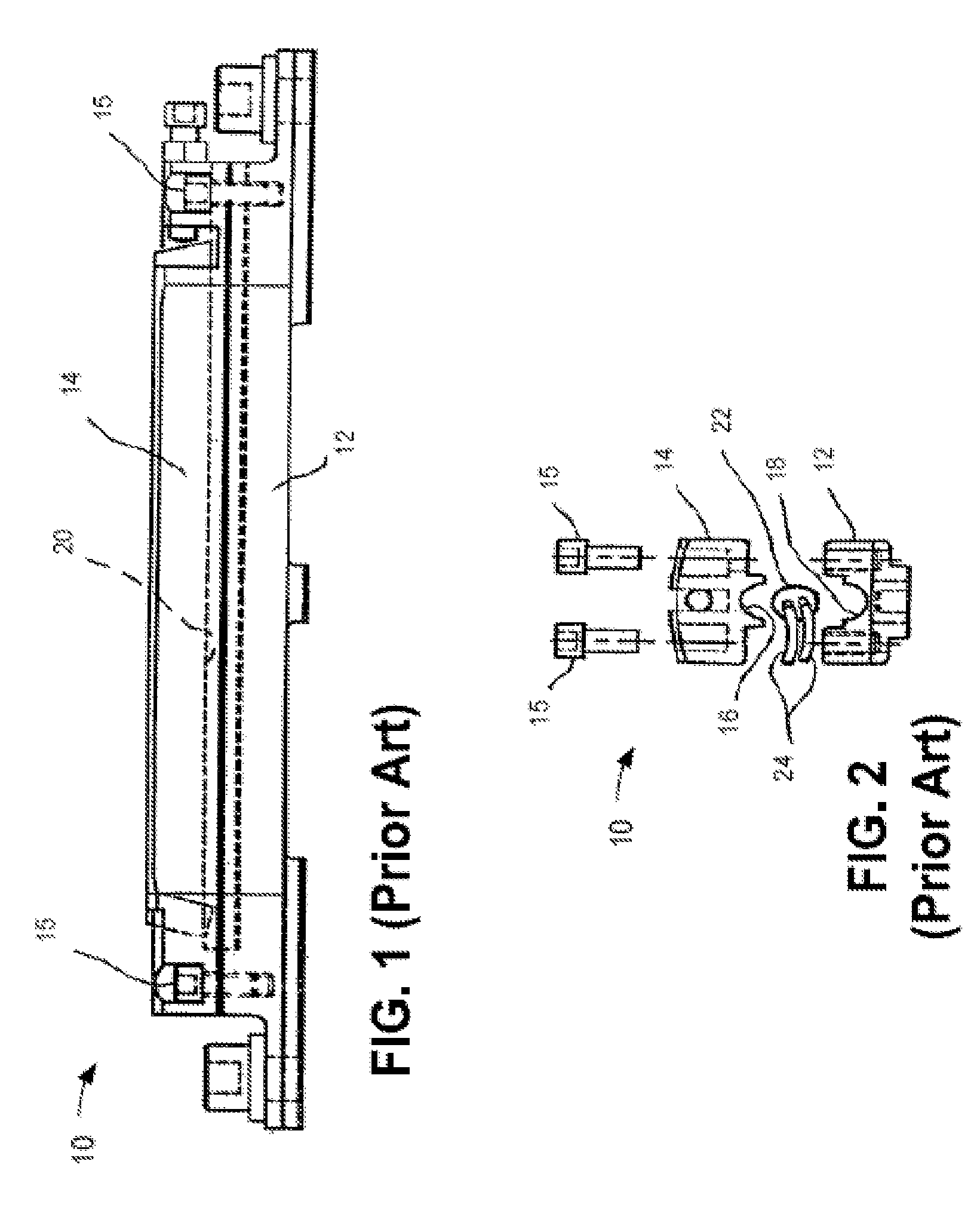
It has been found that the heating element and the wires attached thereto are relatively fragile and are prone to failure.
This was relatively expensive process because of the set-up time required to replace the crimper on the crimping assembly.
Sometimes, replacement of these components required replacement of the entire crimper, which incurred both the set-up time expense and the cost of the new crimper.
Unfortunately, the single heating element 22 in this crimper design does not always provide sufficient heat during a sealing operation.
Another drawback is that the relatively fragile junction between the electrical wires 24 and the heating element 22 is left exposed in this design, as discussed above.

Method used


Image

  • Split crimper for heat sealing packaging material
  • Split crimper for heat sealing packaging material
  • Split crimper for heat sealing packaging material

Examples


Embodiment Construction

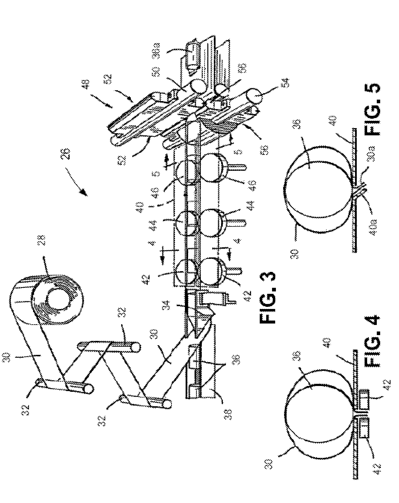
[0021]Referring to the drawings, there is schematically illustrated in FIG. 3 a form, fill, and seal apparatus, indicated generally at 26, in accordance with this invention. The apparatus 26 is generally conventional in the art, and only those portions that are necessary for a complete understanding of this invention will be explained in detail. The apparatus 26 includes means for supporting a roll 28 of a conventional packaging material, such as polypropylene films, saran films, or laminations of a plurality of films. A sheet 30 of the packaging material is payed out from the roll 28 and fed around various rollers 32 to a folding shoe 34. The folding shoe 34 is conventional in the art and is provided to continuously fold the longitudinal edges of the sheet 30 of packaging material about the sides of a plurality of articles 36 that are moved longitudinally along a conveyor 38. The folded sheet 30 of packaging material is then moved along a support surface 40.

[0022]As the folded long...


PUM

PropertyMeasurementUnit
Radiusaaaaaaaaaa

Abstract

A split crimper for use in a crimping assembly for engaging and heat sealing overlapping layers of a packaging material includes a first crimper portion having a crimping surface and a second crimper portion that is secured to the first crimper portion to form a crimper. Portions of the first and second crimper portions cooperate to define an interior cavity, and a heating element is disposed completely within the interior cavity.

Description

CROSS-REFERENCE TO RELATED APPLICATIONS[0001]This application claims the benefit of U.S. Provisional Application No. 60 / 636,468, filed Dec. 16, 2004, the disclosure of which is incorporated herein by reference.BACKGROUND OF THE INVENTION[0002]This invention relates in general to form, fill, and seal packaging machinery of the type in which a continuous sheet of a packaging material is sequentially folded about a series of articles to be packaged, sealed about the articles, and cut into individually sealed packages. More specifically, this invention pertains to an improved crimper for heat sealing overlapping end portions of the sheet of packaging material after it is folded about an article.[0003]The formation of a plurality of individually sealed packages of articles using a single continuous sheet of a packaging material is well known in the art. Briefly, the sheet of packaging material is initially passed through a folding mechanism, which continuously folds the film over on itse...

Claims


Application Information

Patent Timeline
IPC IPC(8): B65B51/16
CPCB29C65/305B29C66/1122B29C66/133B29C66/4312B29C66/4322B29C66/80B29C66/81435B29C66/8167B29C66/83513B29C66/876B65B9/067B65B51/306B29C66/849B29C66/81431B29C65/18B29C53/48Y10T29/49002B29C65/745B29C66/83413B29C66/71B29C66/81422B29K2027/08B29K2023/12
Inventor MONTANO, LOUIS M.SMITH, LARRY E.
Owner LAKO TOOL & MFG
Learn More