
Reduction of noise in a metallic conductor signal pair using controlled line balancing and common mode impedance reduction

a technology of metallic conductors and impedance reduction, applied in one-port networks, line-transmission details, waveguide type devices, etc., can solve problems such as unbalance of pairs and exacerbate nois

Inactive Publication Date: 2010-06-01
ACCELL SYST
View PDF5 Cites 5 Cited by
  • Summary
  • Abstract
  • Description
  • Claims
  • Application Information

AI Technical Summary

Benefits of technology

"The patent text describes a technology for reducing noise in digital subscriber line (DSL) networks, which is a major limitation on the performance of the technology. The main source of noise is cross-coupling of signals in the telephone line over which the DSL signal is transmitted. The invention aims to provide a system that can substantially reduce the amount of noise in the wire pairs, improving the transmission of data. The invention can be adjusted automatically or manually and can be used in conjunction with other electronic components such as transformers or other circuits. The technical effect of the invention is to improve the performance of DSL networks by reducing noise and improving the transmission of data."

Problems solved by technology

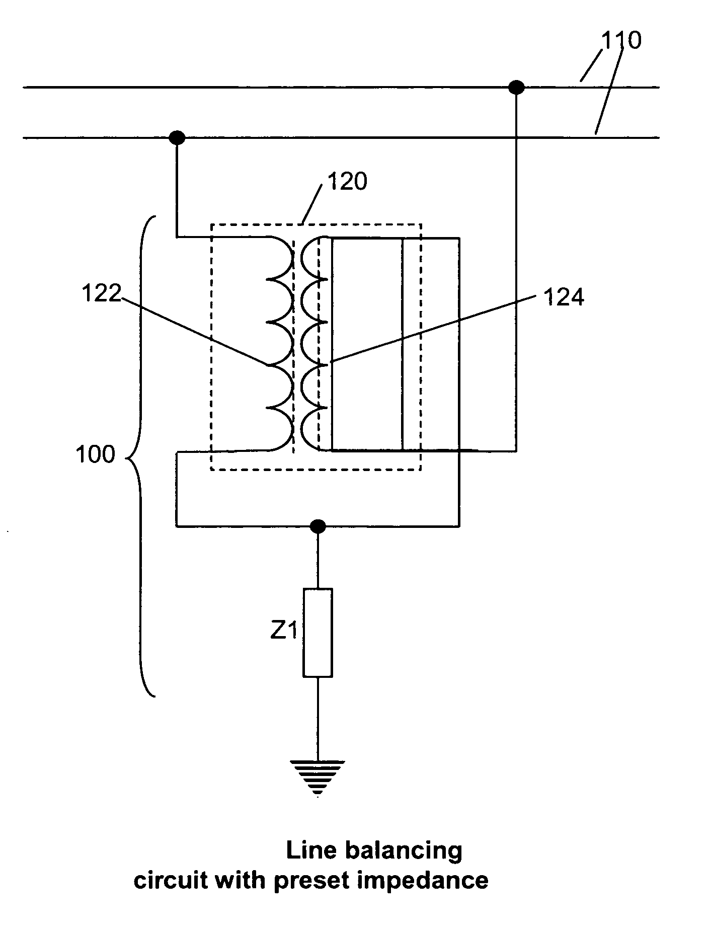
Additionally, Combellack states that an imperfectly matched terminating impedance on a line will cause reflections and standing waves but does not explain how this phenomenon exacerbates noise on the line or how the provision of a matching impedance will mitigate it.
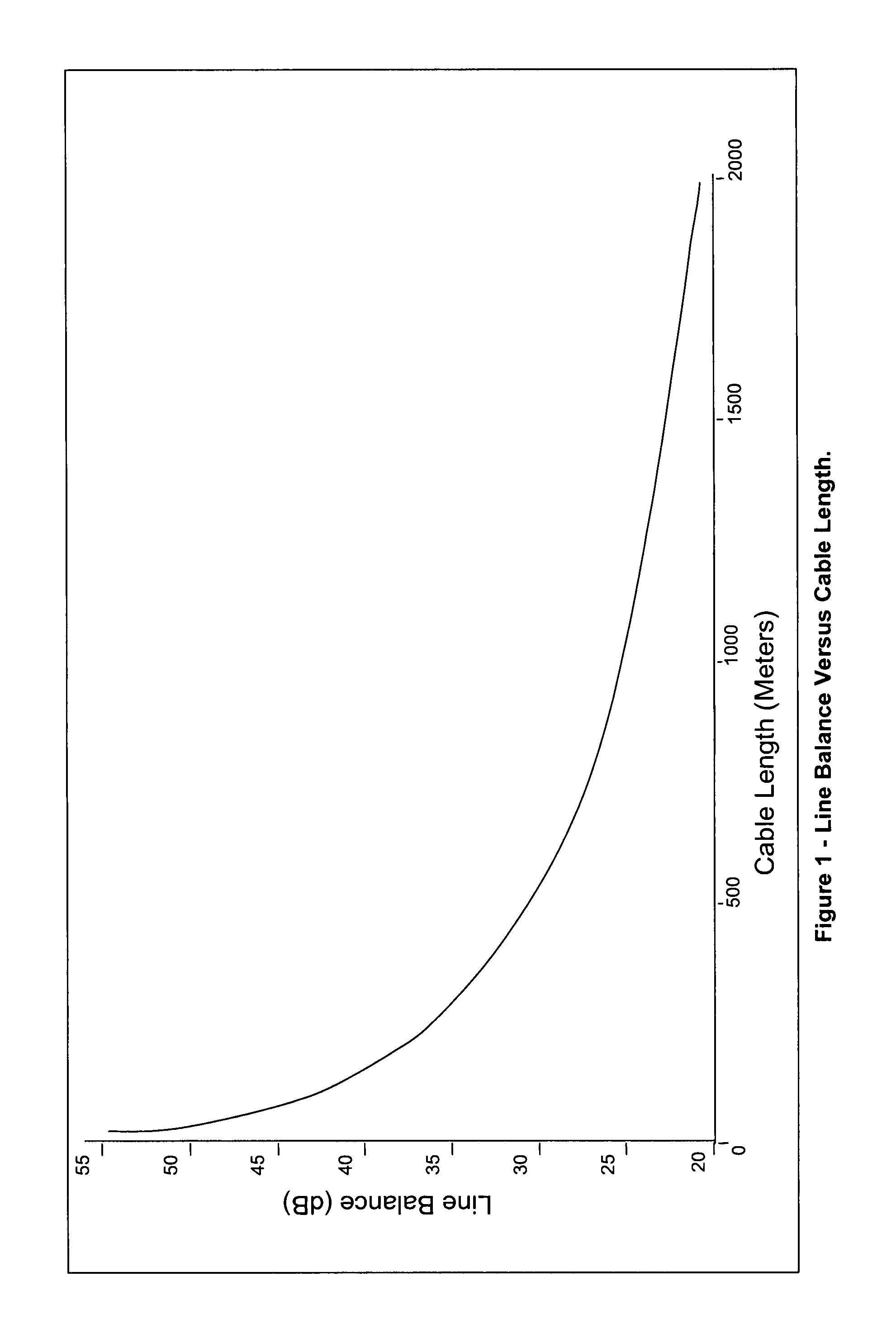
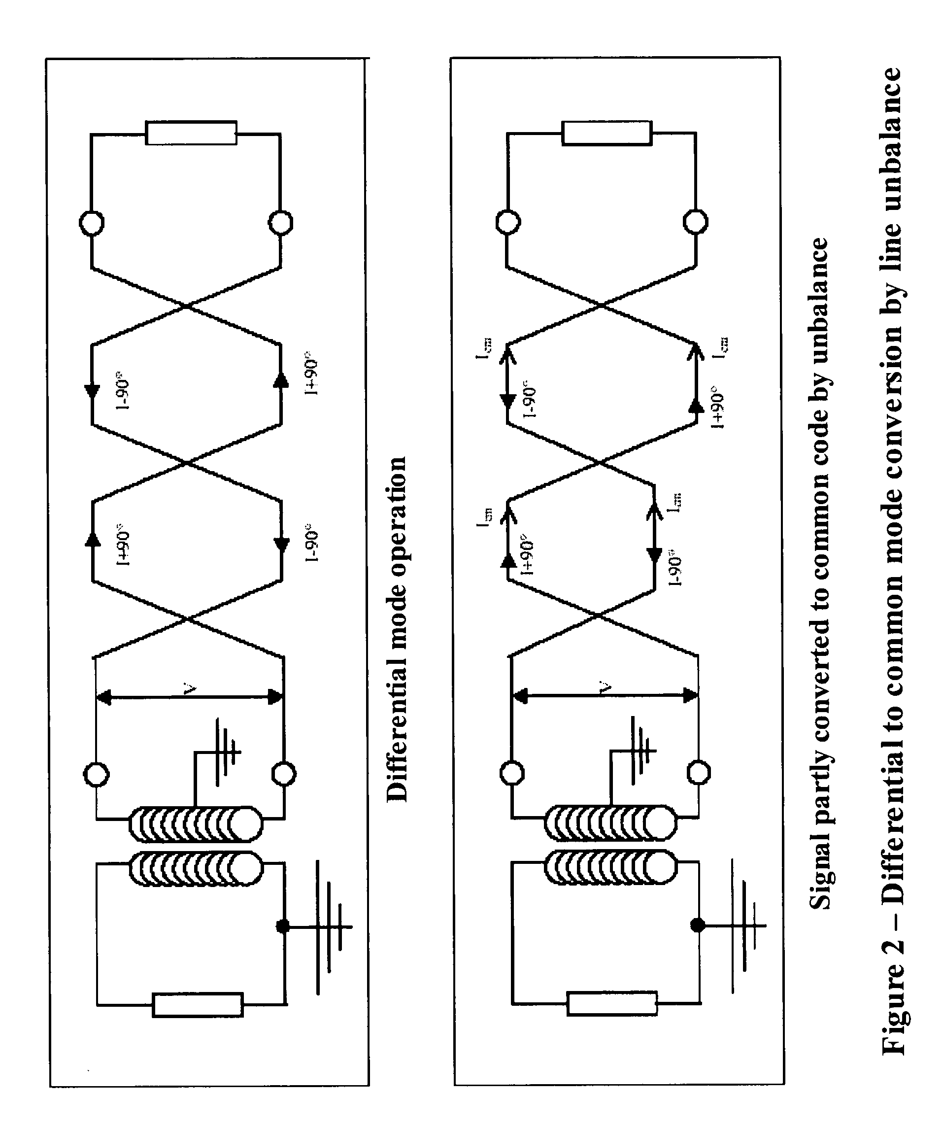
As is well known to practitioners of the art of transmission of signals in the medium of twisted pairs, such a completely balanced line does not, in the real world, exist, since manufacturing faults, installation twists and bends in the wire pair and inequalities in the impedance between each wire of the pair and ground all contribute to inequalities in the parameters of the individual wires of the pair, leading to pair unbalance.

Method used


Image

  • Reduction of noise in a metallic conductor signal pair using controlled line balancing and common mode impedance reduction
  • Reduction of noise in a metallic conductor signal pair using controlled line balancing and common mode impedance reduction
  • Reduction of noise in a metallic conductor signal pair using controlled line balancing and common mode impedance reduction

Examples


Embodiment Construction

Background

[0022]This invention is in the field of telecommunications and involves metallic pair conductors. Such conductors are used to carry signals such as DSL broadband signals, voice signals and any other information containing signals that can be transmitted over a pair of metallic, usually copper, conductors.

[0023]Such signal carrying conductor pairs are normally insulated using polyvinyl chloride or similar plastic insulation and twisted into a double helix in order to reduce the ability of external electromagnetic disturbances from coupling into the line pair in differential mode.

[0024]Because, with the pair twisted, any external interferer whose wavelength is several times the twist length will affect both wires of the pair equally, any signal coupled into one wire during any half twist will be coupled equally into the other wire during the subsequent half twist, and the overall effect on the differential signal between the wires will be extremely small.

[0025]However, this ...


PUM


Abstract

In order to reduce noise on twisted metallic pair signal conductors, circuits are disclosed in which the signal balance between the wires of the pair is significantly improved, thereby reducing the line's susceptibility to external electromagnetic interference and equally reducing its ability to radiate signals into the surrounding medium. Further, the common mode impedance of the wire pair as seen at or close to the junction with the terminating equipment is controlled in order to reduce the ability of signals external to the wire pair to couple into the wire. This reduces noise in the line, as perceived by connected equipment, leading to an increase in the data carrying capacity of the line and the usable length of the line carrying such data.

Description

CROSS-REFERENCE[0001]This Application claims the benefit of U.S. Provisional Patent Application 60 / 812,211, filed Jun. 9, 2006.BACKGROUND OF THE INVENTION[0002]Digital Subscriber Line (DSL) is a technology that enables broadband signals, providing services such as high speed internet access, video-on-demand and real time video conferencing, to be transmitted over ordinary telephone lines from the providers' centrally located DSL Access Module (DSLAM) to DSL modems located at the customer premises.[0003]However, since the inception of DSL, a major limitation on its performance has been the presence of noise in the telephone line over which it operates. Noise combines with the wanted DSL signal and reduces the ability of the receiving modem to demodulate the incoming signal.[0004]Shannon's law (C=W log 2(1+S / N), where C is the channel capacity in bits per second, W is the bandwidth in hertz, and S / N is the signal-to-noise ratio, shows that any increase in noise decreases the data carr...

Claims


Application Information

Patent Timeline
Patent Type & Authority Patents(United States)
IPC IPC(8): H04B3/28H03H7/38
CPCH04L25/0274
Inventor FORTIER, JOHN
Owner ACCELL SYST
Learn More