
Data storage system

a data storage system and data technology, applied in adaptive control, process and machine control, instruments, etc., can solve the problems of data corruption, ineffective mirroring, and affecting the operation of the entire enterpris

Inactive Publication Date: 2010-05-25
SYMANTEC OPERATING CORP
View PDF318 Cites 11 Cited by
  • Summary
  • Abstract
  • Description
  • Claims
  • Application Information

AI Technical Summary

Benefits of technology

"The present invention is a storage management device that allows for the recovery of data at any prior point in time without creating a snapshot of the data store. The device can receive data from other devices connected to a network and store it in physical stores. The device includes a target mode driver, a data classifier, a plurality of storage buffers, a plurality of I / O managers, and a physical store interface. The device can classify the received data and execute further commands to store or retrieve data in the physical stores. The technical effect of the invention is to improve data recovery and minimize data loss in case of corrupting events."

Problems solved by technology

As a result, the disruption or failure of the data storage system can cripple operation of the entire enterprise.
Information technology departments typically deal with a number of problems concerning data storage systems.
Generally, however, these fall into two broad categories: hardware failure and data corruption.
Thus, if a disk failure occurs, the user still has application data residing on the other mirror disks.
However, mirroring is ineffective when data corruption occurs.
Data corruption comes in many forms, but it generally is recognized when the user's application stops functioning properly as a result of data being written to the disk.
There are many possible sources of data corruption such as a failed attempt to upgrade the application, a user accidentally deleting key information, a rogue user purposely damaging the application data, computer viruses, and the like.
Regardless of the cause, mirroring actually works against the user who has experienced data corruption because mirroring replicates the bad data to all the mirrors simultaneously.
Thus, all copies of the data are corrupted.
Additionally, because the disks are continuously updated, a backup of historical data, i.e., a snapshot of the data present in the data storage device at a past time T, can only be created if the system is instructed to save the backup at or prior to time T. Thus, at time T+1 the system is unable to provide a backup of the data current at time T. Further, each unit of storage is saved regardless of whether the data stored in it is unchanged since the time that the previous backup was made.
Such an approach is inefficient and costly because it increases the storage capacity required to backup the data storage device at multiple points in time.
Also, the mirroring approach becomes less efficient and more error prone when employed with larger data storage systems because large systems span hundreds of disks and the systems cannot assure that each disk is backed up at the same point in time.
Consequently, complex and error prone processes are employed in an attempt to create a concurrent backup for the entire data storage system.
This approach suffers, however, from the same shortcomings as mirroring, that is, all snapshots are created at the then current point in time either in conjunction with the users request or as a result of a previously scheduled instruction to create a snapshot of the stored data.
Also, generation of single point in time images generally is a lengthy process.
Because these solutions are only attempts at fixing existing approaches they do not provide a solution that is workable as the capacity of data storage systems continues to increase.

Method used


Image

  • Data storage system
  • Data storage system
  • Data storage system

Examples


Embodiment Construction

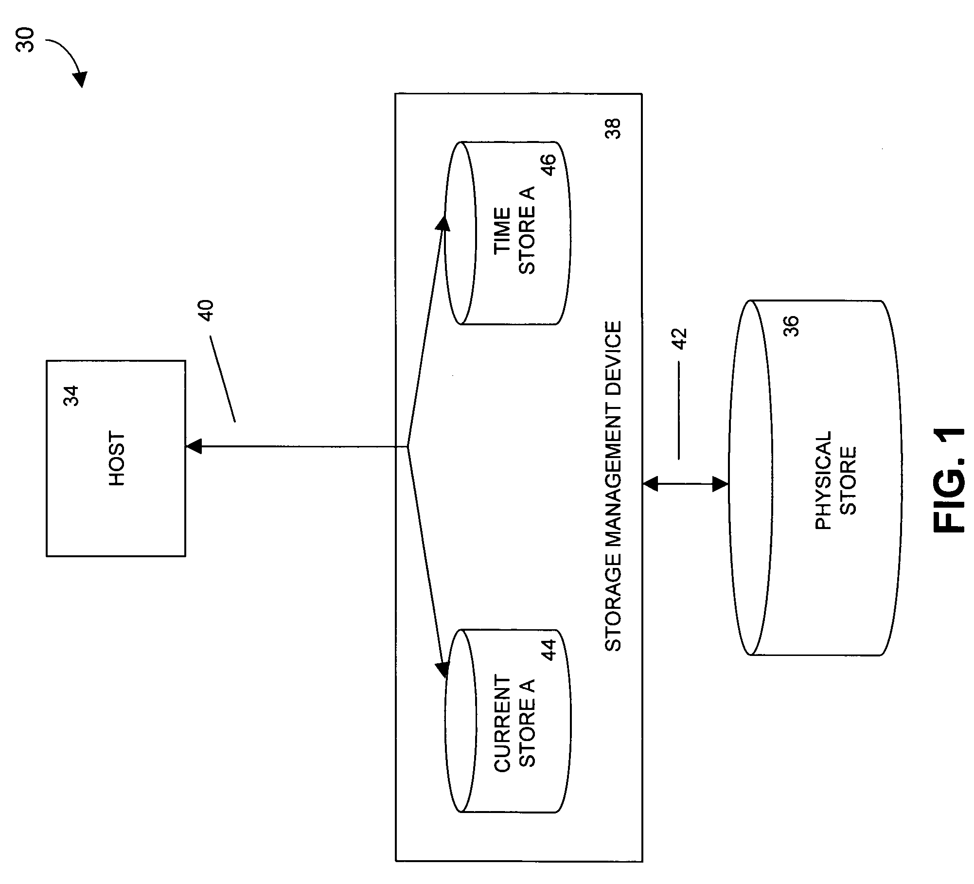
[0061]FIG. 1 provides a general overview of a storage system 30 that allows for the generation of images of a data store from points in time that are prior to a request time. A host 34 communicates with a physical store 36 via a storage management device 38. In one embodiment, the physical store 36 stores digital data. In a version of this embodiment, the physical store 36 is one or more disk drives. For example, the disk drives can be magnetic disk drives, optical disk drives, or a combination of both types of disk drives. In another version of this embodiment, the physical store 36 includes one or more tape drives. The physical store 36 can be one or a combination of drives, or a storage area network. The physical store 36 can itself be a virtual drive presented by any of a variety of storage networks, appliances, or controllers. The physical store 36 can be, for example, a mirrored disk or RAID system, or other storage appliance.

[0062]The host can be any type of network or system...


PUM


Abstract

In a data storage system, a storage management device includes at least a target mode driver, a data classifier in communication with the target mode driver, a plurality of storage buffers in communication with the target mode driver, a plurality of I / O managers in communication with the data classifier, and a physical store interface in communication with the plurality of I / O managers and with the plurality of storage buffers.

Description

CROSS REFERENCE TO RELATED APPLICATION[0001]This application is a continuation-in-part of U.S. patent application Ser. No. 10 / 668,833, filed Sep. 23, 2003, the disclosure of which is hereby incorporated herein by reference in its entirety.TECHNICAL FIELD[0002]The present invention relates to data storage. More particularly, the invention relates to a data storage system architecture.BACKGROUND[0003]Business enterprises rely increasingly on computer systems that allow the sharing of data across a business enterprise. The data storage systems that have evolved to store large amounts of data typically are critically important to an enterprise. As a result, the disruption or failure of the data storage system can cripple operation of the entire enterprise.[0004]Data used by applications running on computer systems are typically stored on primary storage devices (e.g., disks) and secondary storage devices (e.g., tape and cheaper disk drives) for protection. As these applications run, the...

Claims


Application Information

Patent Timeline
Patent Type & Authority Patents(United States)
IPC IPC(8): G06F11/00G06F3/00G06F12/00G06F12/16G06F17/00H04L12/54
CPCG06F11/1435G06F11/1469G06F17/30067G06F11/1461G06F2201/835G06F16/10
Inventor ROWAN, MICHAELRODGERS, KEVINDARCY, JEFF
Owner SYMANTEC OPERATING CORP
Learn More