
Laser beam micro-smoothing

a laser beam and micro-smoothing technology, applied in laser beam welding apparatus, solid-state devices, manufacturing tools, etc., can solve the problems of inconvenient laser annealing system use, inability to remove all small-scale inhomogeneities, and prior-art homogenization techniques cannot, etc., to achieve the effect of smoothing out small-scale inhomogeneities

Active Publication Date: 2010-05-25
COHERENT GMBH
View PDF5 Cites 12 Cited by
  • Summary
  • Abstract
  • Description
  • Claims
  • Application Information

AI Technical Summary

Benefits of technology

"The present invention provides methods, apparatuses, and systems for laser beam micro-smoothing for laser annealing systems. This involves shifting the laser beam in a perpendicular direction to the scanning direction of the system while holding it fixed in the scanning direction. This smooths out small-scale inhomogeneities in the laser beam profile and prevents stripes associated with prior art systems. The technical effects include improved quality of laser annealing and reduced defects in the resulting products."

Problems solved by technology

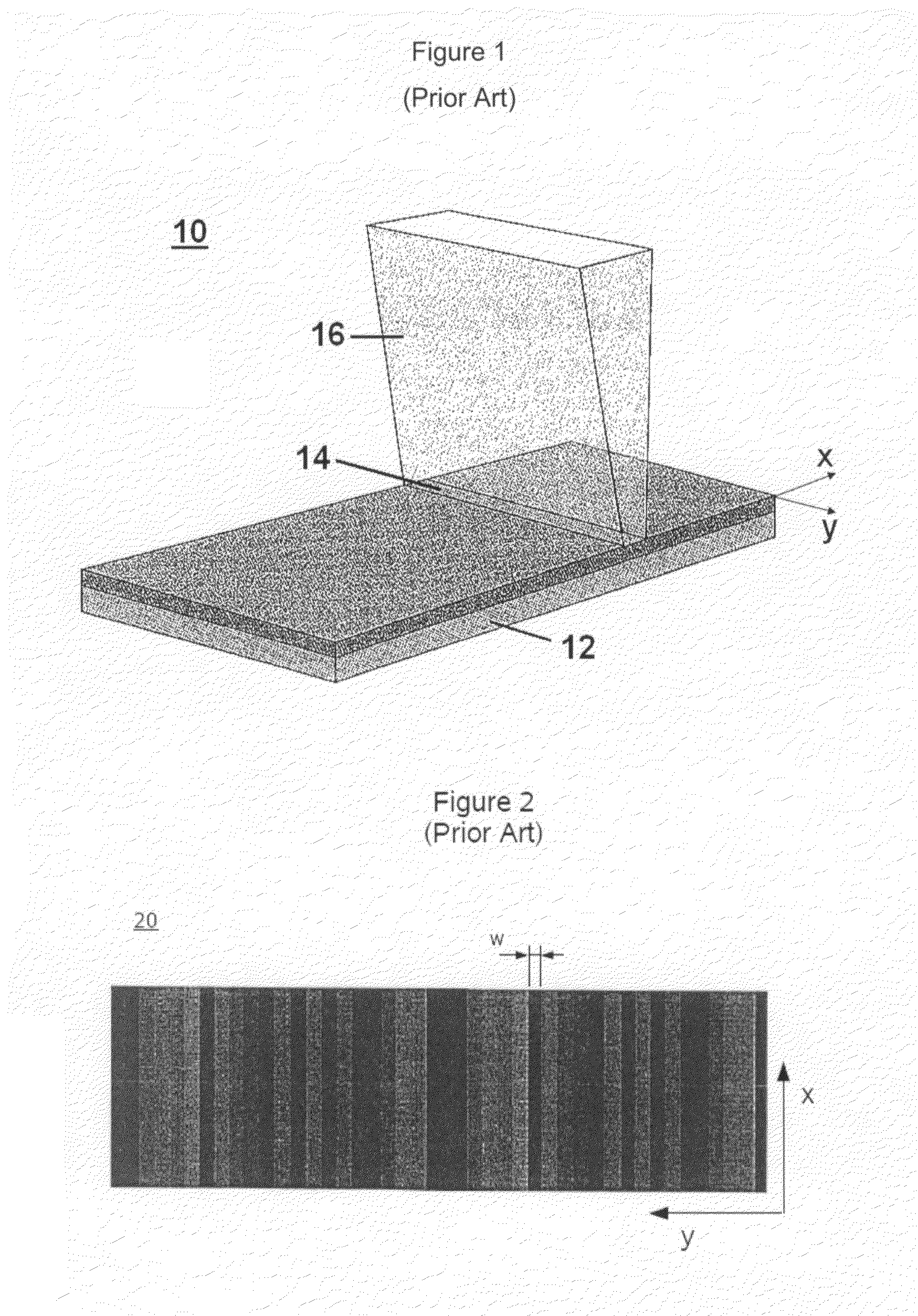
One of the challenges associated with laser annealing is that the illumination field of a laser beam generally has a profile that includes inhomogeneities.
Such inhomogeneities can have various causes including, for example, local defects like absorption or scattering centers in optical components, modulations in the raw laser beam and interference or diffraction from beam homogenizer arrays.
Prior art homogenization techniques cannot, however, remove all small-scale inhomogeneities.
Such systems tend to average out small-scale inhomogeneities, but these systems are not suitable for use with laser annealing systems.

Method used


Image

  • Laser beam micro-smoothing
  • Laser beam micro-smoothing
  • Laser beam micro-smoothing

Examples


Embodiment Construction

[0019]Throughout this document, the following terms shall have the following meanings:

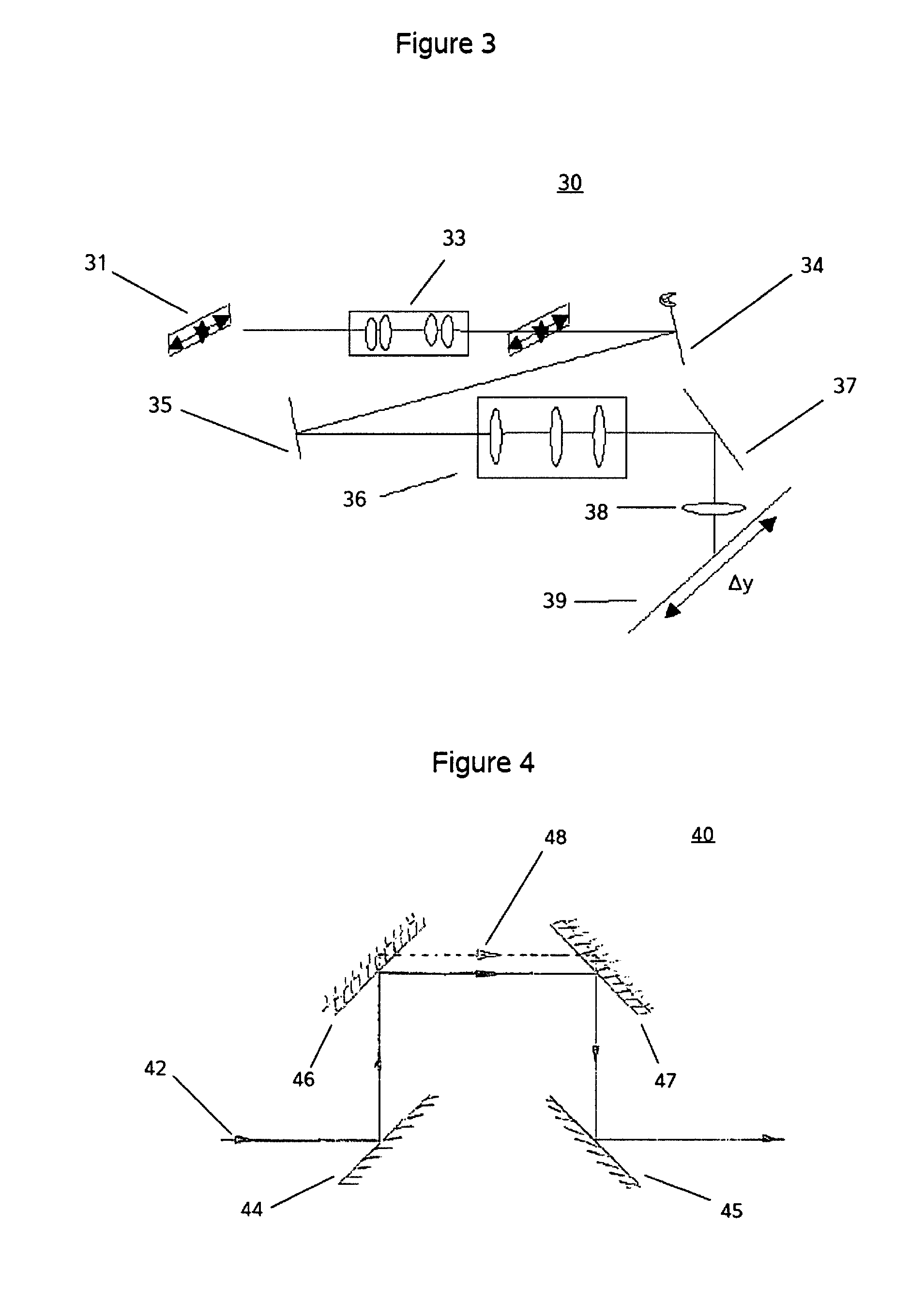
[0020]“x-direction” shall refer to the scanning direction of a laser annealing system;

[0021]“y-direction” shall refer to the direction substantially perpendicular to the x-direction.

[0022]FIG. 3 illustrates a first exemplary embodiment of an apparatus for laser beam micro-smoothing 30 consistent with the present invention. In the apparatus for laser beam micro-smoothing30, a laser beam 31, such as an excimer laser beam or a YAG laser beam, with a substantially rectangular profile is directed through beam homogenizer optic system 33 to a micro-smoothing mirror 34. As homogenizer optic systems are well known in the homogenization art, no further description thereof is presented herein. The micro-smoothing mirror 34 includes an actuator, such as a piezoelectric actuator. Other actuators that are consistent with the present invention include motors with eccentric coupling and magnet-driven levers. In t...


PUM

PropertyMeasurementUnit
scan velocityaaaaaaaaaa
repetition frequencyaaaaaaaaaa

Abstract

The present invention provides laser beam micro-smoothing for laser annealing systems. Laser beam micro-smoothing comprises shifting a laser beam in the direction perpendicular to the scanning direction (y) of a laser annealing system, while holding the laser beam fixed in the direction of scanning (x). The shifting may be accomplished, for example, with a pair of micro-smoothing mirrors. The shifting smoothes out small-scale inhomogeneities in the profile of the laser beam and prevents microscopic stripes associated with prior art laser annealing systems. Because the shifting occurs only in the direction perpendicular to the scanning direction (y), the laser annealing process in not adversely affected.

Description

PRIORITY CLAIM[0001]This application claims priority to U.S. Provisional Patent Application No. 60 / 775,459, filed on Feb. 22, 2006, and U.S. Provisional Patent Application No. 60 / 857,287, filed on Nov. 7, 2006, both of which are incorporated by reference herein.FIELD OF THE INVENTION[0002]The present invention relates generally to laser beam homogenization, and more specifically to smoothing out effects caused by small-scale inhomogeneities in laser beams of laser annealing systems.BACKGROUND OF THE INVENTION[0003]Laser annealing systems are utilized in the production of advanced display technologies such as liquid crystal displays (LCDs) and organic light-emitting diodes (OLEDs). One of the challenges associated with laser annealing is that the illumination field of a laser beam generally has a profile that includes inhomogeneities. Such inhomogeneities can have various causes including, for example, local defects like absorption or scattering centers in optical components, modulat...

Claims


Application Information

Patent Timeline
Patent Type & Authority Patents(United States)
IPC IPC(8): H01L21/84
CPCB23K26/0626B23K26/082B23K26/0738H01L27/1285
Inventor GRAEFE, HOLGERWIEDENBRUCH, UWESCHROEDER, THOMASSIMON, FRANKBERGMANN, ELKO
Owner COHERENT GMBH
Learn More