Sheet feed method, a sheet feeder, and an image forming apparatus incorporating the sheet feeder

a feeder and sheet technology, applied in the direction of thin material processing, article separation, transportation and packaging, etc., can solve the problems of mis-feeding and double-feeding occasionally, the risk of inducing skew increases significantly, and the known method has an important disadvantage, so as to reduce the risk of the element getting damaged, not too much space, and less prone to damage

Active Publication Date: 2010-05-25
OCE TECH
View PDF9 Cites 4 Cited by
  • Summary
  • Abstract
  • Description
  • Claims
  • Application Information

AI Technical Summary

Benefits of technology

[0006]In one embodiment, the blowing of the air creates a pressure difference that forces the element to undertake an upward movement. In this embodiment the mere air blowing action causes the element directly to move in an upward direction. This has the advantage that there is no need for an extra process, next to the air blowing, to provide the element creating the needed lifting force. Next to this, because in this embodiment the element moves upwardly as a direct result of the air blowing process, the prerequisite of an extra force being present only in concurrence with the air blowing action is automatically fulfilled.
[0007]In another embodiment, the element is hinged in the bottom plate. In this embodiment the element is connected to the bottom plate at one end but is able to move upwardly because the connection allows a hinging action of the element. This appears to markedly increase the reliability of the present feeding method, most probably because the element will always come back to its original position when the air blowing action stops.
[0009]In another embodiment, the element is sheet-like. This has the advantage that the element does not take up too much space, and also, that it can easily be situated between the bottom plate and the sheet bundle. In this way, the element will hardly interfere with the process of filling the stacking unit with a new bundle of sheets.
[0010]In a further embodiment the element is a rigid plate that covers a part of the bottom plate. In this embodiment, the element is constituted as a rigid plate in contrast with an element that is constituted as a flexible sheet. This decreases the risk of the element getting damaged by the multiple actions of stacking new bundles of sheets in the stacking unit. A rigid plate is less prone to damaging, such as inducing wrinkles, folds etc., than a sheet-like element.
[0011]In yet a further embodiment, the rigid plate is situated essentially adjacent the air blowing means. Surprisingly it appears that it is sufficient for the rigid plate to extend only in the direct vicinity of the air blowing means. Thus, there is no need for a large rigid plate that extends substantially over the complete side edge of the bundle of sheets. This makes the construction of the stacking unit more simple.
[0012]As a further improvement, the bottom plate can be provided with a recess in which the rigid plate is situated. In this way, the rigid plate does not constitute an obstruction for the lowermost sheets of a new bundle that is being loaded in the stacking unit. The recess can be made just as deep as the rigid plate is thick such that, in essence, the bottom of the stacking unit remains evenly flat. In this way, there is hardly any chance that sheets get damaged because of the presence of the rigid plate.

Problems solved by technology

Many of such media have very smooth surfaces and with sheet feeding methods based on friction, mis-feeds and double-feeds occasionally occur.
The known method however has an important disadvantage.
For the lighter types, typically types of less than 100 grams / square meter, the risk of inducing skew increases significantly when less than 5 to 10 sheets are present.
Heavier types of media seem to be prone to mis-feeds, in particular when narrow paper formats (SEF) are being used.
This prior art solution therefore is far from ideal.

Method used


Image

  • Sheet feed method, a sheet feeder, and an image forming apparatus incorporating the sheet feeder
  • Sheet feed method, a sheet feeder, and an image forming apparatus incorporating the sheet feeder
  • Sheet feed method, a sheet feeder, and an image forming apparatus incorporating the sheet feeder

Examples


Embodiment Construction

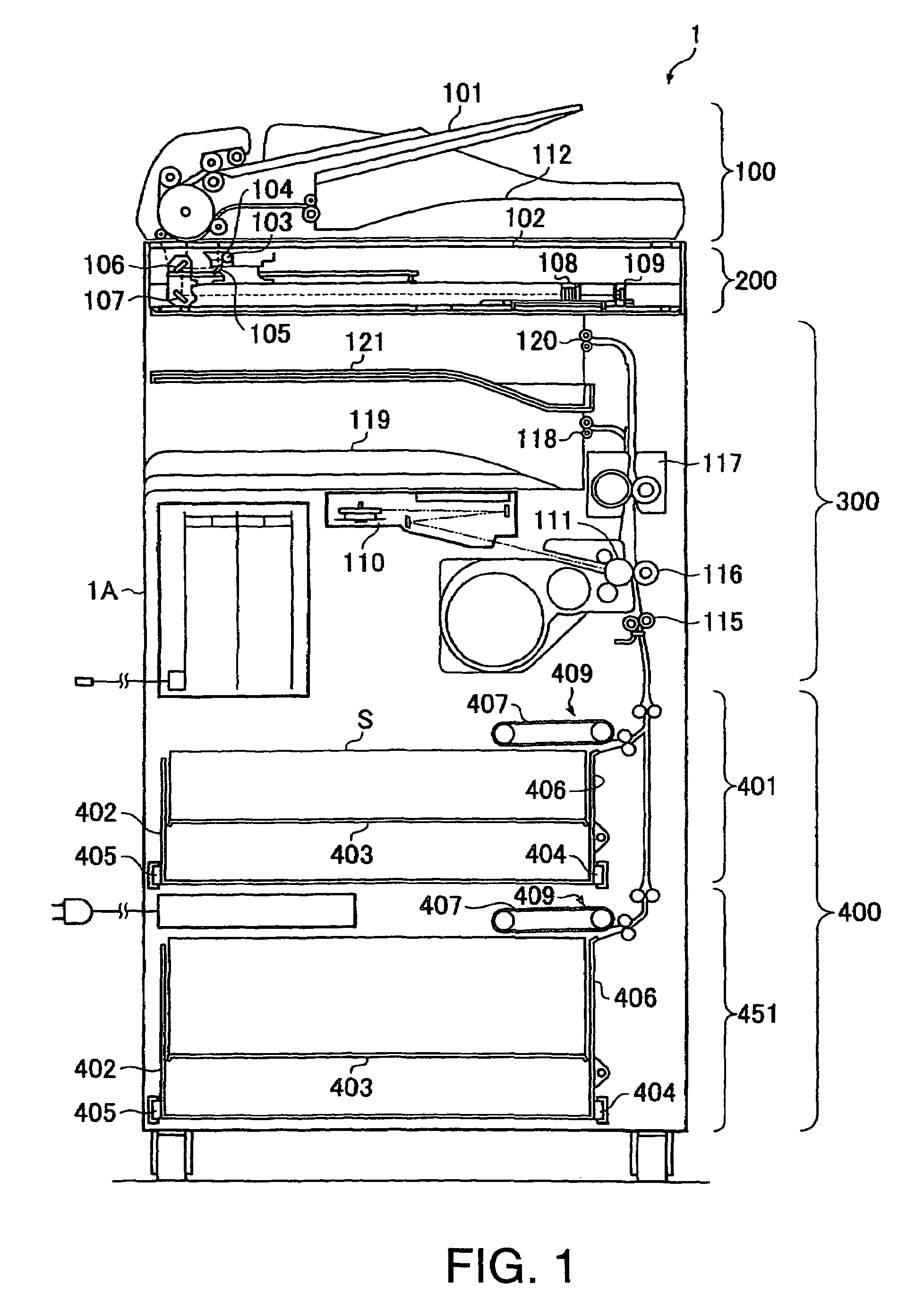
[0018]FIG. 1 represents an imaging device as is known from US 2004 / 0089994 A1 and described elaborately in the paragraphs [0024] to [0034] of this US patent application which paragraphs are incorporated herein be reference. This apparatus includes an image reader 200, a printer 300 and a paper feed section 400. This section has paper decks 401 and 451 that share a paper feeding mechanism.

[0019]The image reader is equipped with a so called ADF 100. This ADF automatically feeds original documents to the image reader 200, in particular from tray 101 to glass platen 102. Thereafter, it discharges the sheets to paper discharge tray 112. When the original passes platen 102 it is read by scanner unit 104. This unit comprises lamp 103, the light of which is reflected via the original to lens 108 and further through mirrors 105, 106 and 107. Ultimately, the light forms an image on image sensor 109. This sensor converts the optical image into image data which data are outputted from the senso...


PUM


Abstract

A method for use in a sheet feeder having a sheet stacking unit with a bottom plate to support a sheet bundle in which air is blown against a side edge of the sheet bundle near the topmost sheets of the bundle, thereby lifting these sheets from the bundle, and separating the uppermost sheet from the bundle, and conveying this sheet away from the bundle, wherein the lifting of the sheets when the bundle is nearly depleted is assisted by forcing an element situated underneath the bundle to push against the bundle solely when air is blown against the side edge of the bundle. A sheet feeder suitable for applying the present method and an imaging apparatus for incorporating the sheet feeder is also provided.

Description

[0001]This application claims the priority benefits of European Patent Application No. 05108187.5 filed on Sep. 7, 2005 which is hereby incorporated by reference.BACKGROUND OF THE INVENTION[0002]The present invention pertains to a sheet feed method for use in a sheet feeder having a sheet stacking unit provided with a bottom plate to support a sheet bundle whenever air is blown against a side edge of the sheet bundle near the topmost sheets of the bundle, thereby lifting these sheets from the bundle, separating the uppermost sheet from the bundle, and conveying this sheet away from the bundle. The present invention also pertains a sheet feeder and an imaging apparatus incorporating the sheet feeder.[0003]A sheet feed method is known from US patent application 2004 / 0089994 A1. This method has been devised in order to be able and reliably feed a very broad range of recording media from the same sheet stacking unit. Nowadays, in printing rooms there are growing requests to form images ...

Claims


Application Information

Patent Timeline
Patent Type & Authority Patents(United States)
IPC IPC(8): B65H3/14
CPCB65H1/16B65H3/128B65H3/48B65H3/14B65H2515/342B65H2515/34
Inventor GRUNTJES, MARINUS T. W.BINDELS, MAURICE J. M.
Owner OCE TECH
Why Eureka
Try Eureka