Method for operation of a gas turbine group

Active Publication Date: 2010-05-25
PHOENIX BIOPOWER AB
View PDF21 Cites 35 Cited by
  • Summary
  • Abstract
  • Description
  • Claims
  • Application Information

AI Technical Summary

Benefits of technology

[0012]A further purpose of the invention is to propose a configuration that enables a first gas turbine group, which may be a traditional stand-alone gas turbine unit, to be operated as a humidified cycle. Thereby, the traditional gas turbine unit may be an existing device which can be complemented / retrofitted with the second gas turbine unit. Alternatively, the traditional gas turbine unit can be newly manufactured from a well-known and extensively tested design that has been produced and in operation previously. In this way, the newly manufactured first gas turbine group is well known, has desirable operational characteristics, a good efficiency and an existing maintenance and service infrastructure.

Problems solved by technology

However, in practice, a traditional “dry” gas turbine, which is optimised for operation with dry air as the working fluid, exhibits unacceptable operational characteristics if large amounts of water are injected into the working fluid.
Of those few gas turbines that do utilise steam injection, the amount of steam that may be injected into the working fluid is limited, and consequently not all the steam available from the heat recovery steam generator may be utilised.
If humidified cycles are to be realised, a large and costly re-design of the gas turbine machinery is necessary to accommodate the changed flow distribution and imbalance between the volume capacity of the compressor and turbine.
In addition, traditional gas turbines often cool the hot temperature regions of the turbine by utilising cold cooling air from the compressor; thus, the compressor has a certain over-capacity in the form of this cooling air.
This further increases the degree to which the gas turbine must be re-designed, as the imbalance between the volume capacity of the compressor and turbine becomes even larger when steam cooling is introduced.

Method used


Image

  • Method for operation of a gas turbine group
  • Method for operation of a gas turbine group
  • Method for operation of a gas turbine group

Examples


Embodiment Construction

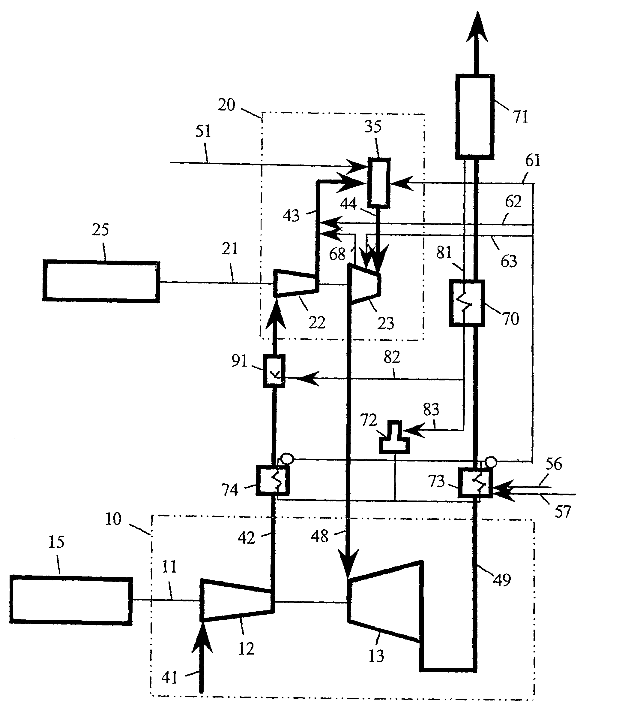
[0040]FIG. 1 shows a first gas turbine group 10 comprising of an axle 11, which is connected to a compressor 12 and a turbine 13. The first gas turbine group 10 is dimensioned and designed as a traditional gas turbine that is meant for conventional operation with just air as the working fluid. An electricity generator 15 is shown connected to the axle 11. Alternatively, work can be extracted from the first gas turbine group 10, via the axle 11, to another device.

[0041]FIG. 1 also shows a second gas turbine group 20 that includes a turbine 23, a compressor 22 and an axle 21, which is shown connected to an electricity generator 25 or to another device that can utilise the work transferred through the axle 21.

[0042]The axle 11, which is connected to the first gas turbine group 10, as well as axle 21, which is connected to the second gas turbine group 20, can both be connected to a common device which utilises the net work provided by the two groups.

[0043]Air is taken in from the atmosp...


PUM


Abstract

A method of operating a gas turbine power plant comprising of a first gas turbine group, consisting of a compressor and a turbine which are connected mechanically with one another, and a second gas turbine group, including a combustion device, which is placed in the gas flow stream between the first group's compressor and turbine, whereby the second gas turbine group consists of a compressor, a fuel injection device, a combustion chamber and a turbine, whereby the second gas turbine group's compressor and turbine are mechanically coupled to one another and at least one of the gas turbine groups having a device for the extraction of work, whereby the fact that a first flow of water and / or steam is heated with heat from the flue gas from the first group's turbine, that further amounts of water and / or steam are heated with heat from a gas stream that is compressed by the first group's compressor, and the produced water and / or steam is injected into the gas stream in such amounts that at least 60% of the oxygen content of the air in the stream is consumed through combustion in the combustion device, and in that the combustion gas that is fed into the turbine of the second gas turbine group has a pressure in the range 50-300 bar.

Description

CROSS REFERENCE TO RELATED APPLICATIONS[0001]The present application is a 35 U.S.C. §371 national phase conversion of International Application No. PCT / SE2004 / 000822 filed May 28, 2004, which claims priority from Swedish patent application No. 0301585-6 filed May 30, 2003.BACKGROUND OF THE INVENTION[0002]This invention concerns a method for the operation of a gas turbine cycle whose art is presented in the introduction of the first claim.[0003]It is already known that the same operational conditions are, in certain cases, reached by a gas turbine cycle of the art described in claim 1, whereby water and / or steam is heated with flue gases from the expander of the said gas turbine cycle during operation.[0004]In traditional gas turbines, air is used as the working fluid. The intake air is compressed to high pressure after which fuel is mixed with the compressed air. This mixture is then combusted in a combustion chamber and expanded through a turbine. This turbine produces work, a part...

Claims


Application Information

Patent Timeline
IPC IPC(8): F02C3/30F01K21/04F02C6/18F02C7/08F02C7/143F23L7/00
CPCF01K21/047F02C3/305F02C7/08F02C7/143F23L7/005F02C6/18Y02E20/14Y02E20/344F05D2260/2322
Inventor HANSSON, HANS-ERIKWESTERMARK, MATS
Owner PHOENIX BIOPOWER AB
Why Eureka
Try Eureka