Method for producing a vehicle axle

a technology of vehicle axles and axles, which is applied in the field of vehicle axle production, can solve the problems of difficult optimization, difficult to achieve such a solution, and heavy forged products, and achieve the effects of increasing the torsional rigidity of the member, constant material thickness, and optimizing the material thickness of the construction elemen

Inactive Publication Date: 2010-05-25
VOLVO LASTVAGNAR AB
View PDF11 Cites 3 Cited by
  • Summary
  • Abstract
  • Description
  • Claims
  • Application Information

AI Technical Summary

Benefits of technology

[0013]The forging operation comprises a first step in which a pair of first cooperating die pads form the material in the first blank such that it acquires a predetermined, varying height in a vertical plane along its longitudinal extent, the blank acquiring its principal basic shape in this plane. The blank is then moved to another forging press which performs a second step in which a pair of second cooperating die pads form the material in the first blank such that it acquires a predetermined, varying thickness along one or more of the side surfaces, bottom surface and upper edge surfaces of the profile along its longitudinal extent. This second step is repeated one or more times in further forging presses in which successive die pads form the blank until it has acquired its final shape. It is thereby possible to re-distribute the material of the blank both in its cross section and along its longitudinal extent. Through suitable configuration of the die pads, the blank can be formed freely, as far as the forging process allows, along both its inner and its outer periphery.
[0017]The final result is a hollow, elongated construction element comprising a first section having a cross-section substantially in the form of a hat profile of a predetermined, varying width, height and material thickness along its length, and a second section that has an essentially constant material thickness and is joined together with the first section along the side surfaces of the hat profile. This configuration offers greater opportunity to optimize the material thickness of the construction element compared to known construction methods. Firstly, the material can be distributed such that maximum thickness is obtained where the loads on the construction element are greatest; and secondly, a material displacement towards the periphery of the construction element is obtained thereby increasing the member's torsional rigidity. A hollow profile of this type also offers considerable weight savings compared with a corresponding traditionally forged product.
[0020]As previously mentioned, it is possible to optimize the production method so that the maximum material thickness of such a front axle beam is obtained in connection with fastening points and regions which are to be subjected to external forces and moments. The method makes it also possible to adapt the cross section of the front axle beam such that it acquires essentially the same outer contours in both the vertical and horizontal planes as a traditionally forged, solid beam. By giving the outer contours of the beam the same so-called “offset” (shape in the horizontal plane along the length of the beam) and “drop” (shape in the vertical direction) as a standard beam for a certain vehicle, it can be used without requiring modification being made to existing vehicle design. It is also possible to maintain existing fastening points (so-called “interfaces”) for steering spindle holders, springs and the like which interact with such beams.

Problems solved by technology

This applies especially to forged products, which can be heavy and difficult to optimize because of limitations inherent to the tools used in their production.
With traditional forging methods, it is difficult to achieve such a solution.
As previously stated, the drawback with the solution is that the web of the beam, for the greater part, is centrally located, which has little effect upon the torsional rigidity.
Although it is possible with this method to obtain a beam with higher torsional rigidity, it also creates a number of problems.
Even if the material is distributed radially, viewed further out from the center of the beam, the possibility of controlling the material thickness is very limited.
One drawback with this solution is, like the example above, that the distribution of the material along the length of the profile cannot be controlled.
For technical reasons of casting practice, there are restrictions, however, in terms of maximum and minimum material thickness, as well as the need for strengthening ribs, complicated casting cores and the like in order to allow a sufficiently advanced profile to be cast.
In addition to this, there are further restrictions in terms of a practical choice of material, as well as financial implications for the unit price of the axle beams owing to the heavily increased costs that a casting process entails.

Method used


Image

  • Method for producing a vehicle axle
  • Method for producing a vehicle axle
  • Method for producing a vehicle axle

Examples


Embodiment Construction

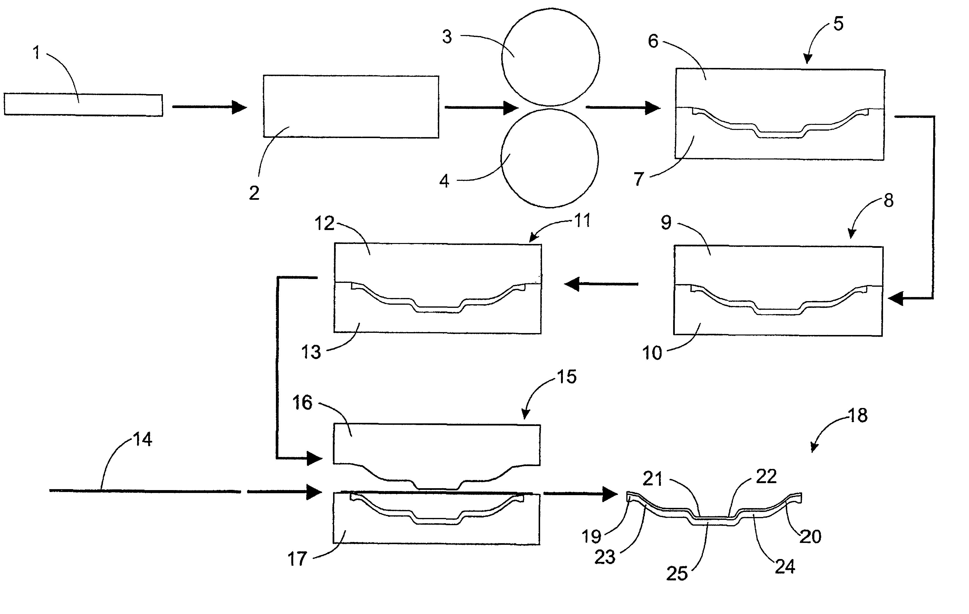
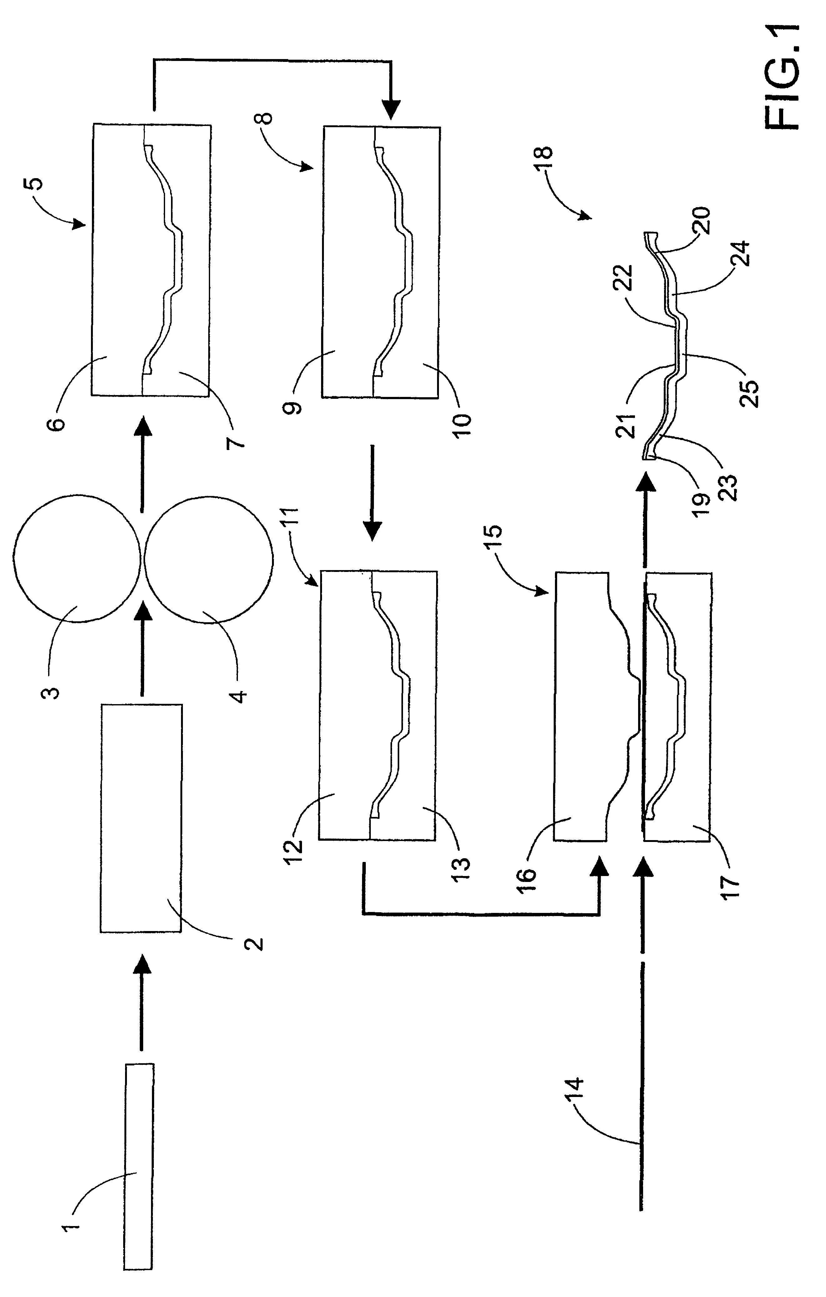
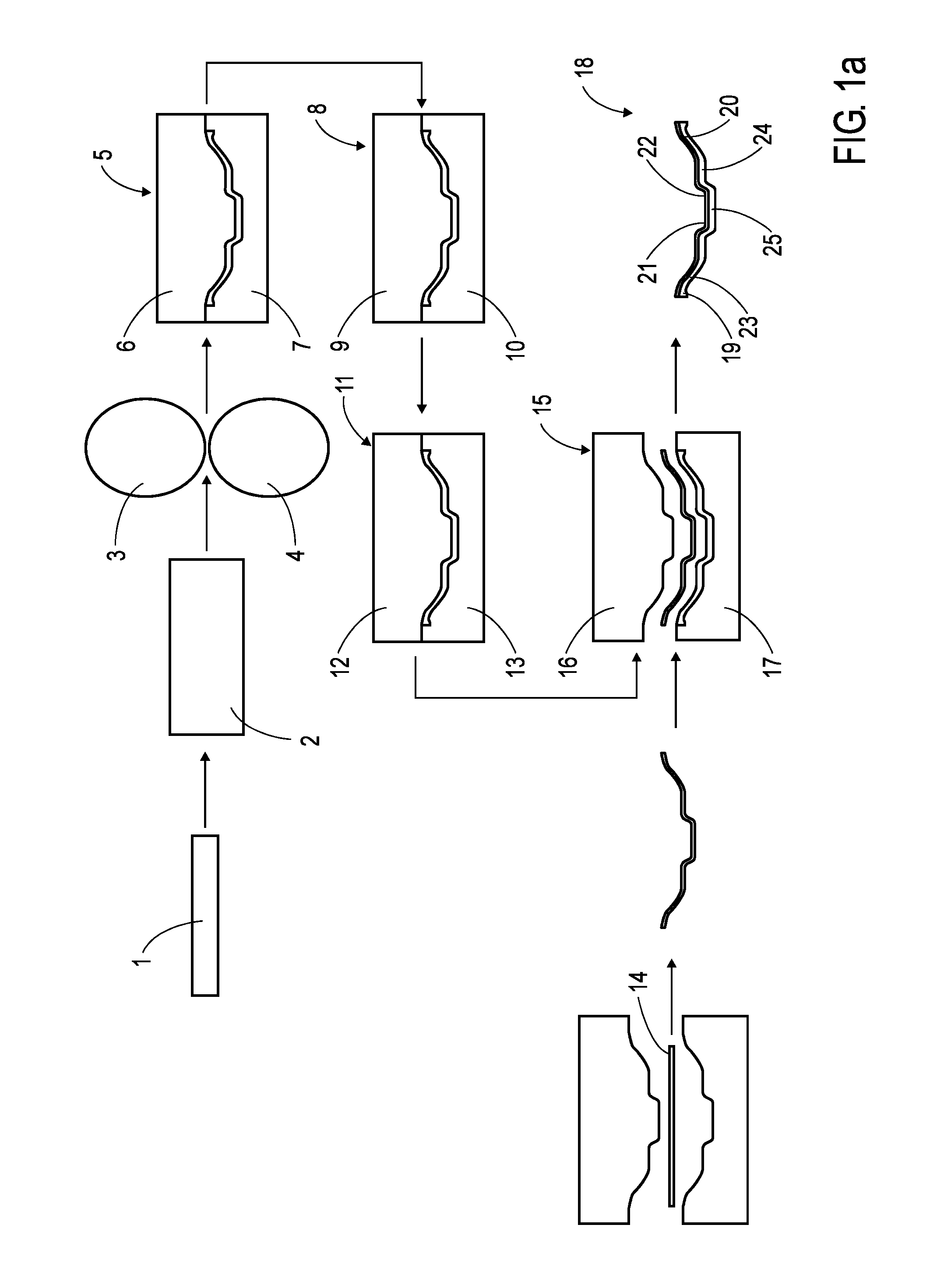
[0027]FIG. 1 diagrammatically illustrates a preferred embodiment of a method conducted according to the teachings of the present invention which includes a number of steps for the production of a composite hollow construction element, exemplarily, a front axle beam for heavy vehicles.

[0028]A first blank 1, which has been cut to a predetermined length, is directed through an induction furnace 2 in which it is heated to working temperature. Where, for example, air-hardening, microalloyed steel is used, the blank is heated to 1250-1300° C., and preferably to 1280° C. Once the correct temperature has been reached, the blank is directed through a pair of profiled rollers 3, 4, which are profiled (exteriorly adapted) to give the blank 1 a suitable initial cross section along its longitudinal extent. Through suitable configuration of the respective profiles of the rollers 3, 4, an intermediate product is obtained, whose cross section and material thickness varies along the length of the bl...


PUM

PropertyMeasurementUnit
temperatureaaaaaaaaaa
heightaaaaaaaaaa
widthaaaaaaaaaa

Abstract

Method and apparatus for providing a hollow, elongated construction element, for example for use as a vehicle front axle. The method includes (1) directing a first blank through a furnace (2) for heating the blank to a working temperature. The blank is directed between a pair of rollers (3, 4) having profiled surfaces, the blank being preformed in one or more steps to form an intermediate product having a predetermined profile along its longitudinal extent. The blank is fed to a forging press having a number of cooperating die pads, the blank being worked in a plurality of steps (5, 8, 11) to form a substantially finished product, having a cross section substantially in the form of a hat profile of predetermined varying height, width and material thickness along its length. A second blank (14), having essentially the same profile as the hat profile of the first blank in the dividing plane of the cooperating die pads, is placed in connection with the hat profile. In a later step (15), the first (1) and the second blank (14) are joined together, at least along their respective edges, to form a composite hollow construction element (18). One embodiment of the disclosed invention is also the construction element that is produced according to the above-described method.

Description

CROSS REFERENCE TO RELATED APPLICATIONS[0001]This present application is a continuation patent application of International Application No. PCT / SE02 / 00501 filed 18 Mar. 2002 which was published in English pursuant to Article 21(2) of the Patent Cooperation Treaty, and which claims priority to Swedish Application No. 0101046-1 filed 23 Mar. 2001. Both applications are expressly incorporated herein by reference in their entireties.BACKGROUND OF INVENTION[0002]1. Technical Field[0003]The invention relates to a method for producing hollow, composite construction elements, preferably intended for use in vehicles, and a construction element produced according to the method.[0004]2. Background Art[0005]In many fields, there is currently a demand for weight-optimized products with maintained functioning and strength. This applies especially to forged products, which can be heavy and difficult to optimize because of limitations inherent to the tools used in their production.[0006]One example...

Claims


Application Information

Patent Timeline
Patent Type & Authority Patents(United States)
IPC IPC(8): B21D53/88B21D39/00B60B35/16B21C37/08B21K1/06B21K21/00B23K20/02B23P15/00B60B35/08
CPCB21C37/0803B21C37/0815B21K1/06B21K21/00B23K20/023B60B35/08B23P15/00Y10T29/49622Y10T29/49893Y10T29/49968Y10T29/49865Y10T29/49829
Inventor PREIJERT, STEFANFUKS, LEON
Owner VOLVO LASTVAGNAR AB
Why Eureka
Try Eureka