
Downhole tool delivery system

a tool and tool technology, applied in the field of downhole tool delivery systems, can solve the problems of time-consuming and expensive undertaking, compounding the tool deployment task, and deploying downhole tools such as bridge plugs, frac plugs, and downhole monitoring devices within the casing of downhole wells

Active Publication Date: 2010-04-27
EXXONMOBIL UPSTREAM RES CO
View PDF31 Cites 28 Cited by
  • Summary
  • Abstract
  • Description
  • Claims
  • Application Information

AI Technical Summary

Benefits of technology

The patent describes an apparatus for use in oil and gas wells that includes a wellbore, a sealed housing, and a tool attachment portion. The sealed housing contains a processor and a location sensing system that can communicate with the well casing to determine its position as the housing moves along the well casing. The apparatus also includes a well plug with a second flow through core that can be used to control material flow through the first and second cores. The sealed housing can also secure a perforation device interface and activation module for activating a perforation device in response to the well plug being set in position. The technical effects of this invention include improved wellbore positioning and control, as well as improved wellbore perforation capabilities.

Problems solved by technology

Deployment of downhole tools, such as bridgeplugs, fracplugs, and downhole monitoring devices within casings of downhole well bores, is a time consuming and expensive undertaking.
At times, the tool being deployed hangs up in the casing, or the wire line becomes tangled and lodged in the casing, or may become disassociated from the tool, requiring retrieval and redeployment of the tool, thereby compounding the tool deployment task.
Accordingly, challenges remain and a need persists for improvements in methods and apparatuses for use in accommodating effective and efficient deployment of downhole tools.

Method used


Image

  • Downhole tool delivery system
  • Downhole tool delivery system
  • Downhole tool delivery system

Examples


Embodiment Construction

[0030]Detailed descriptions of the preferred embodiments are provided herein. It is to be understood, however, that the present invention may be embodied in various forms. Various aspects of the invention may be inverted, or changed in reference to specific part shape and detail, part location, or part composition. Therefore, specific details disclosed herein are not to be interpreted as limiting, but rather as a basis for the claims and as a representative basis for teaching one skilled in the art to employ the present invention in virtually any appropriately detailed system, structure or manner.

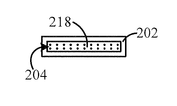
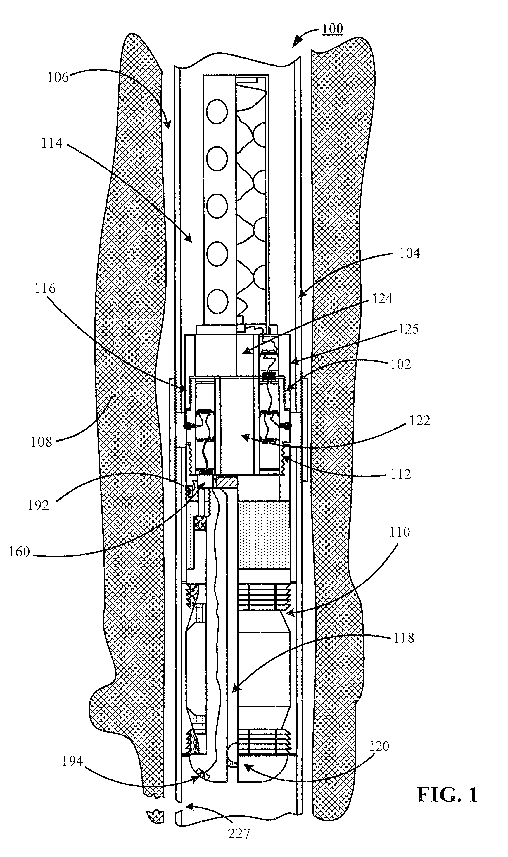
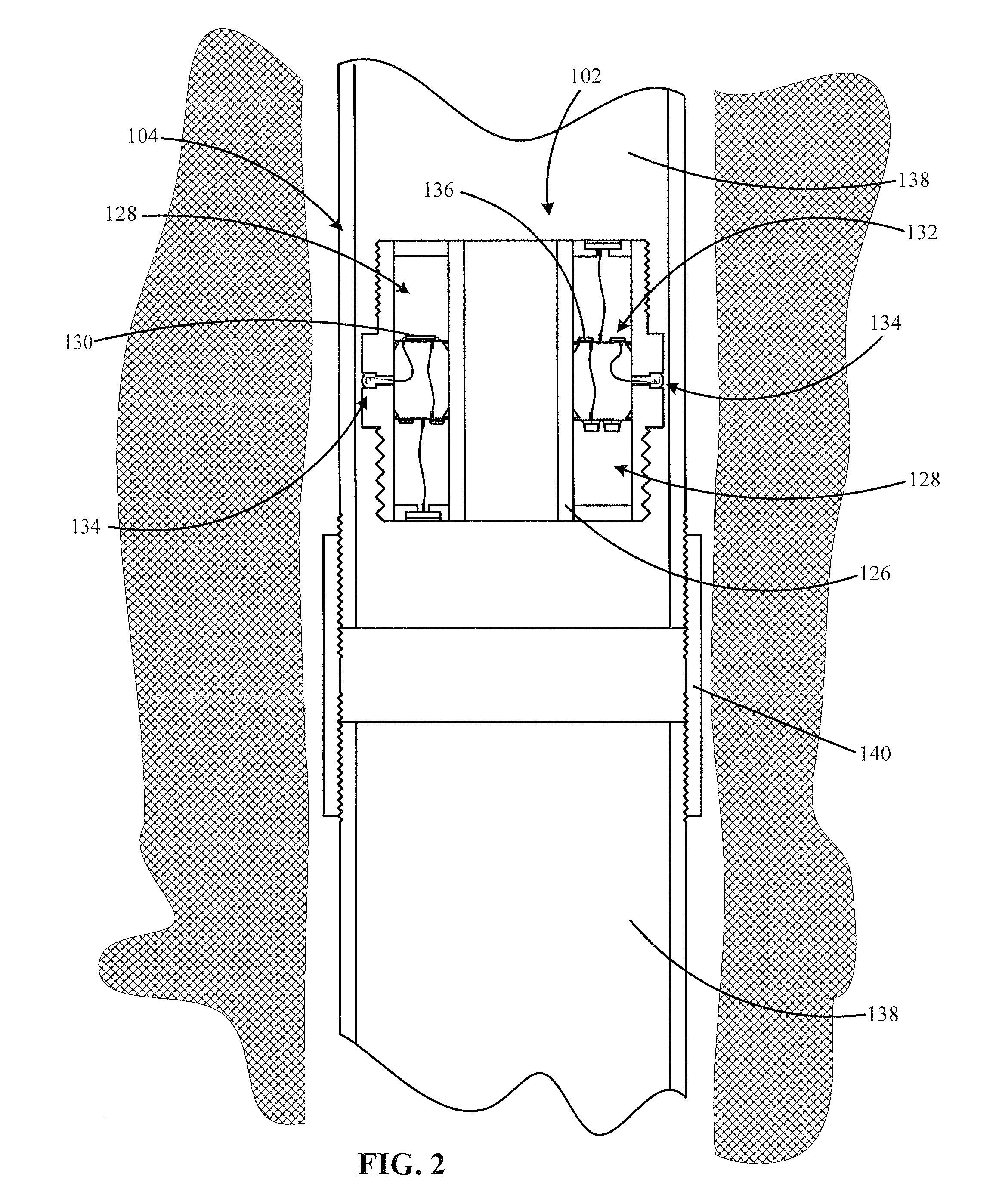
[0031]Reference will now be made in detail to one or more examples of the invention depicted in the figures. Each example is provided by way of explanation of the invention, and not meant as a limitation of the invention. FIG. 1 shows an inventive downhole tool delivery system 100 that preferably includes a depth determination device 102, in sliding confinement within a well casing 104 of a...


PUM


Abstract

An apparatus for use in deployment of downhole tools is disclosed. Preferably, the apparatus includes at least an in-ground well casing, a housing providing a hermetically sealed electronics compartment, a tool attachment portion, and a first flow through core. The housing is preferably configured for sliding communication with the well casing. The hermetically sealed electronics compartment secures a processor and a location sensing system, which communicates with the processor while interacting exclusively with features of the well casing to determine the location of the housing within the well casing. A preferred embodiment further includes a well plug affixed to the tool attachment portion, the well plug includes a second flow through core capped with a core plug with a core plug release mechanism, which upon activation provides separation between the second flow through core and the core plug, allowing material to flow through said first and second flow through cores.

Description

FIELD OF THE INVENTION[0001]This invention relates to downhole tool delivery systems, and in particular, but not by way of limitation, to a wellbore casing depth sensing system having an ability to deliver downhole tools while interacting exclusively with features of the casing to determine the location of the downhole tool within the casing, relative to the surface.BACKGROUND[0002]Deployment of downhole tools, such as bridgeplugs, fracplugs, and downhole monitoring devices within casings of downhole well bores, is a time consuming and expensive undertaking. Attaining a desired predetermined depth requires continuous monitoring of the amount of wire line, jointed tubing or coiled tubing secured to the tool that has been dispensed to transport the tool to the desired depth. At times, the tool being deployed hangs up in the casing, or the wire line becomes tangled and lodged in the casing, or may become disassociated from the tool, requiring retrieval and redeployment of the tool, the...

Claims


Application Information

Patent Timeline
Patent Type & Authority Patents(United States)
IPC IPC(8): E21B29/00E21B47/00
CPCE21B33/12E21B47/122E21B47/09E21B43/116E21B47/13
Inventor STRICKLAND, DENNIS A.
Owner EXXONMOBIL UPSTREAM RES CO
Learn More