
Inductive quench for magnet protection

a quench system and magnet protection technology, applied in the field of quench systems, can solve problems such as substantial ac losses, and achieve the effect of effective conducting hea

Active Publication Date: 2010-04-20
MASSACHUSETTS INST OF TECH
View PDF17 Cites 178 Cited by
  • Summary
  • Abstract
  • Description
  • Claims
  • Application Information

AI Technical Summary

Benefits of technology

This approach effectively reduces the reactive power needed to initiate a quench across a large fraction of the superconducting coil, minimizing mechanical stresses and preventing damage by achieving uniform temperature distribution and reducing peak temperatures during energy dissipation.

Problems solved by technology

The only requirement is that the AC field be well coupled to the main coil to result in substantial AC losses (due to hysteresis, coupling or eddy current heating).

Method used


Image

  • Inductive quench for magnet protection
  • Inductive quench for magnet protection
  • Inductive quench for magnet protection

Examples


Embodiment Construction

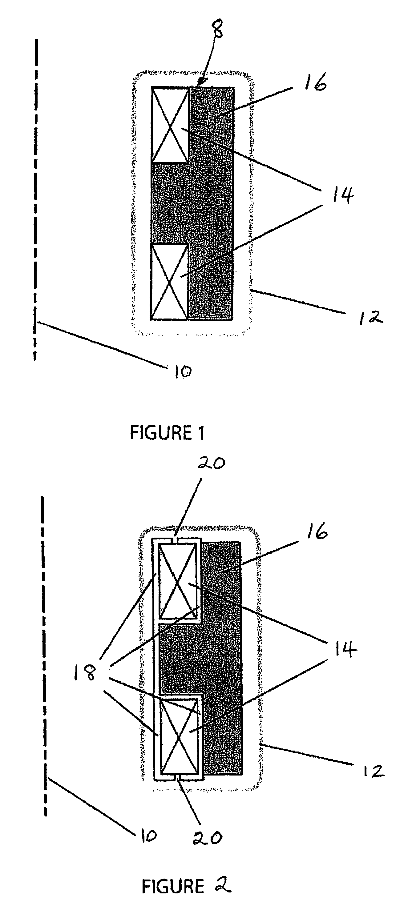
[0021]The purpose of the invention is to decrease the reactive power required to drive AC magnetic fields that result in sufficient heating of a superconducting winding so that a quench is generated in a short time interval over a large fraction of the main superconducting coil.

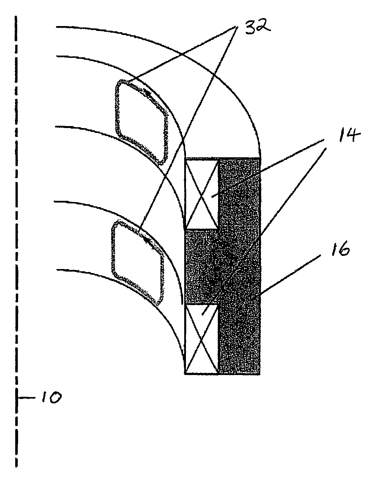
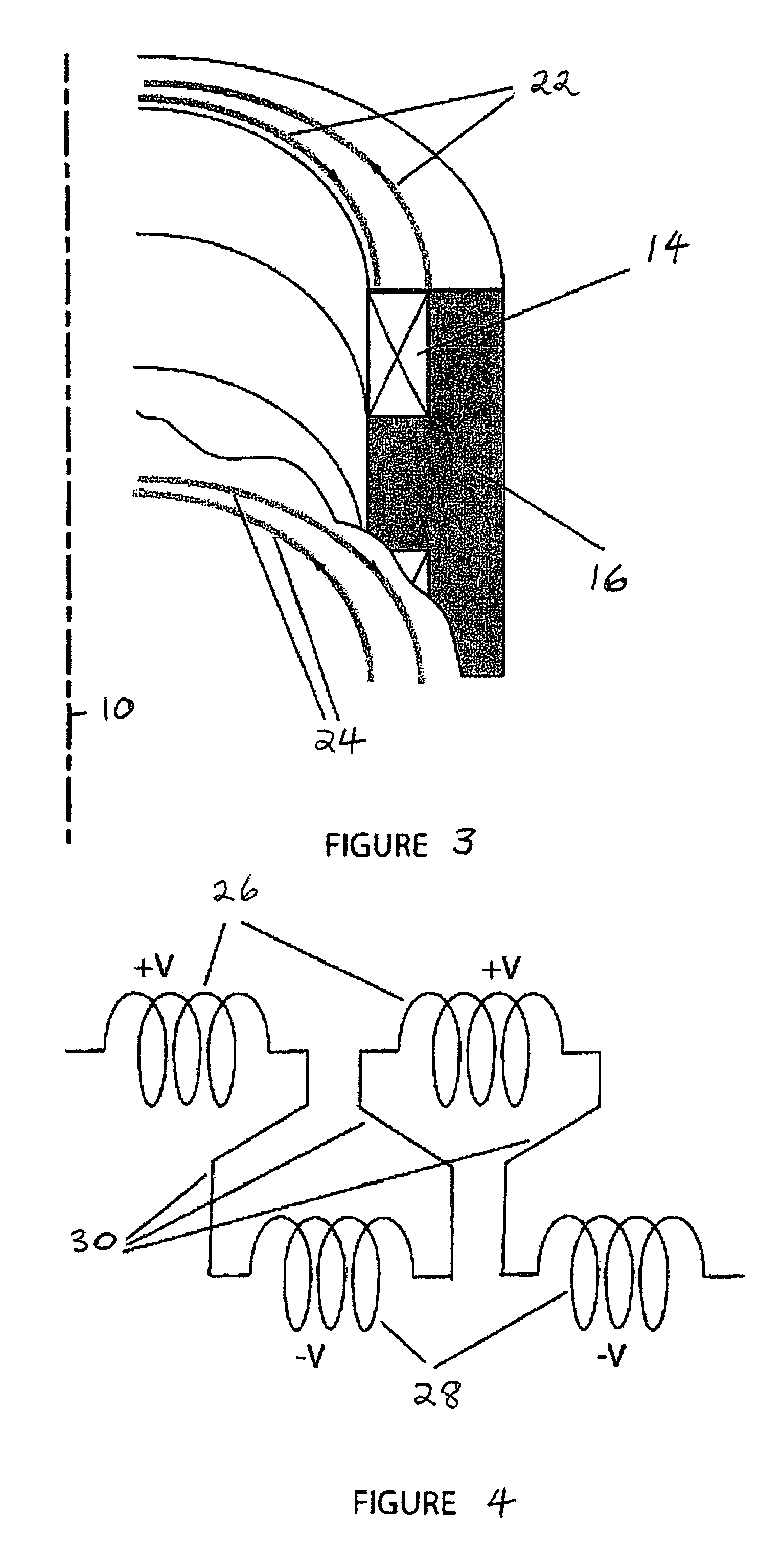
[0022]Embodiments of the invention described below can be interpreted in terms of either magnetic fields or mutual inductances. In order to decrease the required energy in the AC magnetic field used to heat the main DC superconducting magnet, the AC magnetic fields are oriented, in some embodiments, normal to the steady state main field. By design then, the ratio of the energy in the AC magnetic field to that of the main DC magnetic field scales as (IAC / ISC)2, where IAC and ISC are the AC coils' and the main superconducting coil's currents respectively. Since the ratio IAC / ISC is much smaller than one, the energy in this configuration is much smaller than in conventional inductive heaters, where rippling osci...


PUM

PropertyMeasurementUnit
frequencyaaaaaaaaaa
AC magnetic fieldaaaaaaaaaa
AC magnetic fieldsaaaaaaaaaa

Abstract

A coil system for inductively heating a superconducting magnet in order to provide an internal energy dump by uniformly quenching a high performance superconducting magnet. The quench-inducing system uses AC magnetic fields that require negligible reactive power. The system is especially suited for inducing a relatively uniform quench in dry superconducting magnets.

Description

BACKGROUND OF THE INVENTION[0001]This invention relates to a quench system for protecting superconducting magnets. High performance superconducting magnets operate at high current densities with zero or near zero resistivity. The high current densities and zero or near zero resistance minimize the size of the magnet winding, allowing for more compact magnets and increased magnetic fields.[0002]If the temperature, field, or current is too high in some region of the superconductor, it loses its superconducting properties and becomes resistive or normal. Typically superconductors in the normal state are much more resistive than copper. The current flows in the high conductivity metal (usually copper or aluminum) that usually shunts the superconductor. The region of the winding where electrical current flows in the normal conducting material region due to the superconducting material losing its superconducting ability is called the quench zone or the normal zone. In the normal zone the ...

Claims


Application Information

Patent Timeline
Patent Type & Authority Patents(United States)
IPC IPC(8): H02H7/00H02H9/00H01F7/00H05B6/02H05B6/04H05B6/10H10N60/20
CPCH01F6/02Y02E40/68H02H7/001H01L39/14Y02E40/60H10N60/20H02H9/00G01R33/3815
Inventor SCHULTZ, JOEL HENRYMYATT, LEONARDBROMBERG, LESLIEMINERVINI, JOSEPH V.ANTAYA, TIMOTHY
Owner MASSACHUSETTS INST OF TECH
Learn More