
Centrifugal pump

Inactive Publication Date: 2010-04-20
JOSTRA AG
View PDF19 Cites 59 Cited by
  • Summary
  • Abstract
  • Description
  • Claims
  • Application Information

AI Technical Summary

Benefits of technology

[0025]The object of the present invention is to create a centrifugal pump with a bearingless rotor, in which in a simple way that protects fluid, the rotor can be stabilized in the axial and radial directions and has high efficiency.
[0032]The radial stabilization of the rotor can be done purely passively on the basis of reluctance forces. The hydrodynamic radial shear, which urges the rotor out of the center of the rotary motion, should be minimized. To that end, the projection area of the rotor in the x-y / z plane is preferably kept minimal as an active face of radially destabilizing pressure forces. It is determined solely by the thickness of the coverings of the rotor. The rotor may preferably be made entirely of paramagnetic and / or ferromagnetic material and permanently magnetized. In that case, no encapsulation of discrete permanent magnets is necessary, which contributes to increasing the radial projection area. A further provision against radial instability is to provide a circular, rotationally symmetrical annular gap, which divides the rotor side chambers from a spiral conduit that carries the pumped flow tangentially away. As a result, a constant flow resistance to the fluid that emerges from the rotor is generated, and hence a radial pressure force on the rotor that acts uniformly via the circumference of the rotor is generated. The third provision against radial instability comprises a suitable design of the spiral conduit that carries the flow away, in which radially destabilizing pressure forces in the region of the tongue are avoided.
[0033]The drive of the pump is preferably done in the form of a permanently excited electrical synchronous machine, whose rotor is formed by the rotor of the pump, which is located between two symmetrical stators with a wide air gap. The stators may be rotated counter to one another, as can the permanent magnet regions of the rotor that are split into two planes. The pole coverings and the topology of the electromagnetic flux linkage can be optimized so that with the least mass of magnetic material, high efficiency and low waviness is attained, that is, high constancy of the torque and low axial rigidity of the magnet system, thereby making the hydrodynamic suspension of the rotor possible. Simultaneously, the magnetic reluctance forces between the stators and the rotor are utilized for centering the rotor radially.

Problems solved by technology

Blood pumps of conventional design, in which the drive of the rotor is done by an electric motor with a supported shaft that penetrates the pump housing and is provided with a shaft seal are therefore unsuited for permanent implantation.
Furthermore, the pump rotor in the housing must be guided by end journal bearings that are bathed with blood; these bearings wear and from local heating denature blood proteins and are capable of activating the coagulation system, which can lead to emboli from abrasion and clots.
Any possible use of this principle must take Earnshaw's theorem into account, which states that it is not possible to keep a body floating in space in a stable position by means of constant magnetic, electrical, or gravitational fields.
Any apparent position of equilibrium is in fact unstable, since the body is in that case at a maximum of potential energy.
Besides the complex production, this embodiment requires an elongated gap between the rotor and the housing with only inadequate purging and high energy consumption for the axial stabilization, which must counteract the considerable hydraulic axial shear that is generated by an open impeller.
Because of the externally located stators for the drive and positional regulation, this pump requires a relatively large amount of installation space.
Problems also arise in versions with open impellers because of the high hydrodynamic axial shear, which unavoidably occurs.
To overcome them, additional active or passive magnet bearings as well as hydrodynamic aids in the form of nozzles, impact plates, inflow tubes, flow resistors, and sealing gaps are proposed, all of which increase the complexity of the system, lessen its efficiency, create flow stasis zones, induce high shear stresses, and are thus entirely unsuitable for the realization of a blood pump, especially for permanent implantation.
In this version as well, there is the risk of high shear stresses and the generation of flow stasis zones on the back side of the rotor.
All these proposals share the disadvantage of mechanical wall contact between the rotor and the housing, with the known consequences of damage to the blood.
This disadvantageously makes for an extremely complex mechanical construction of the rotor and multiple stators as well as extremely complex regulating electronics with an additional energy requirement, especially since to avoid high axial destabilizing forces, an ironless motor has to be used, which because of its poor efficiency heats up sharply.
A disadvantage here is the long axial length of the narrow, eccentric bearing gap, in which high shear stresses are operative, and which for being washed out requires auxiliary blades and a purging circuit from the high- to the low-pressure side of the pump.
This arrangement involves the familiar risks of high shear and inadequate heat dissipation, which lead to traumatization of the blood.
Other disadvantages of this version are that the open pump rotor is surrounded on all sides relative to the housing by narrow gaps, in which high viscous friction prevails.
Moreover, the housing is complicated to manufacture.
The embodiment of a covered pump rotor shown in FIG. 20, with a surface structured in wedgelike shape in sectors, does not overcome these disadvantages, especially since it cannot be seen what path the blood is supposed to take to flow through such a rotor.
Once again, the disadvantages are damage to the blood and a complicated housing construction.
This pump must be embodied with two inlets, or the inflow must be diverted inside the pump by 180°; the result is large wetted internal surfaces as well as questionable hydrodynamic stability.
If that does not suffice, an active magnet bearing is provided for radial stabilization, but this represents additional electronic complication and expense.
A critical assessment of the prior art discussed consequently shows that the contactless rotation of the rotor of a centrifugal pump in the housing is attained either by means of high complexity and expense for sensors and electromagnetic regulation, or at the cost of a high hydrodynamic load on the blood from damaging shear stresses.

Method used


Image

  • Centrifugal pump
  • Centrifugal pump
  • Centrifugal pump

Examples


Embodiment Construction

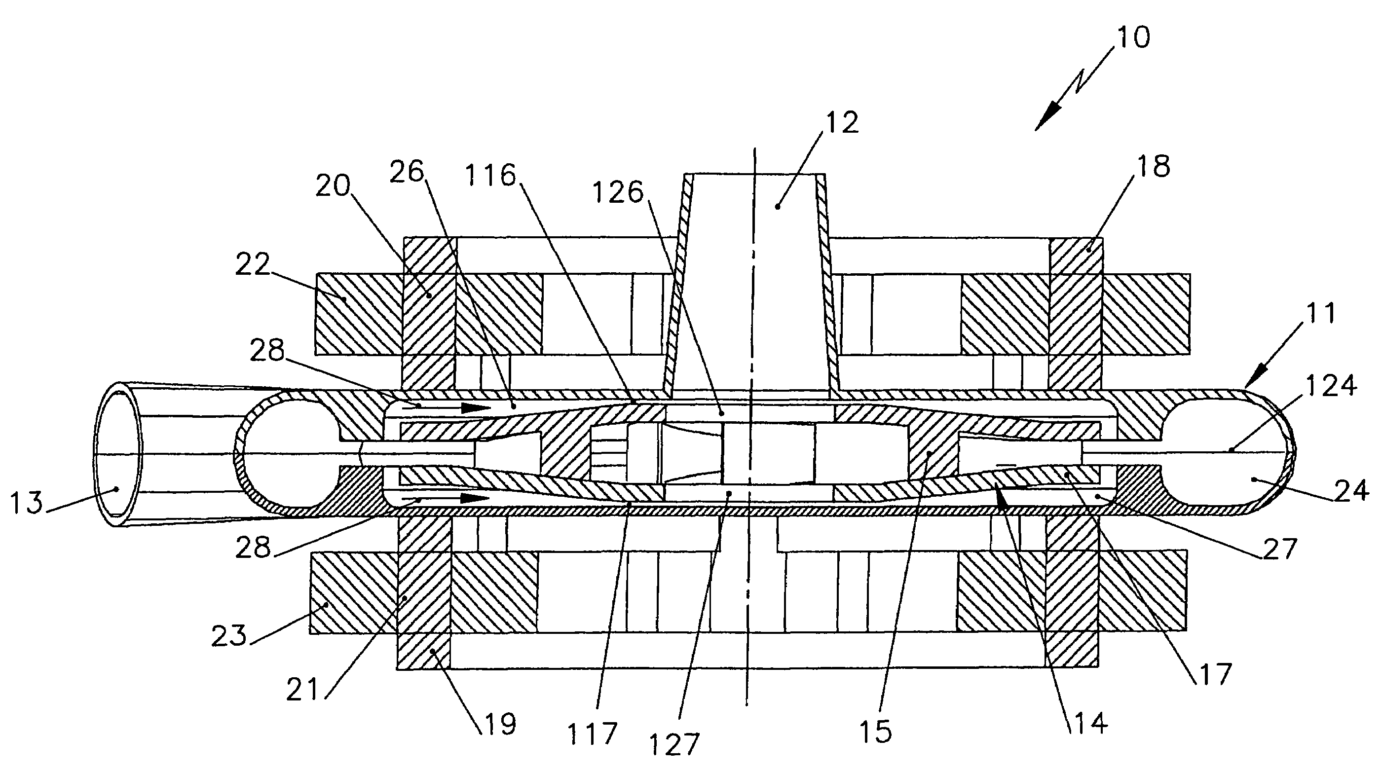
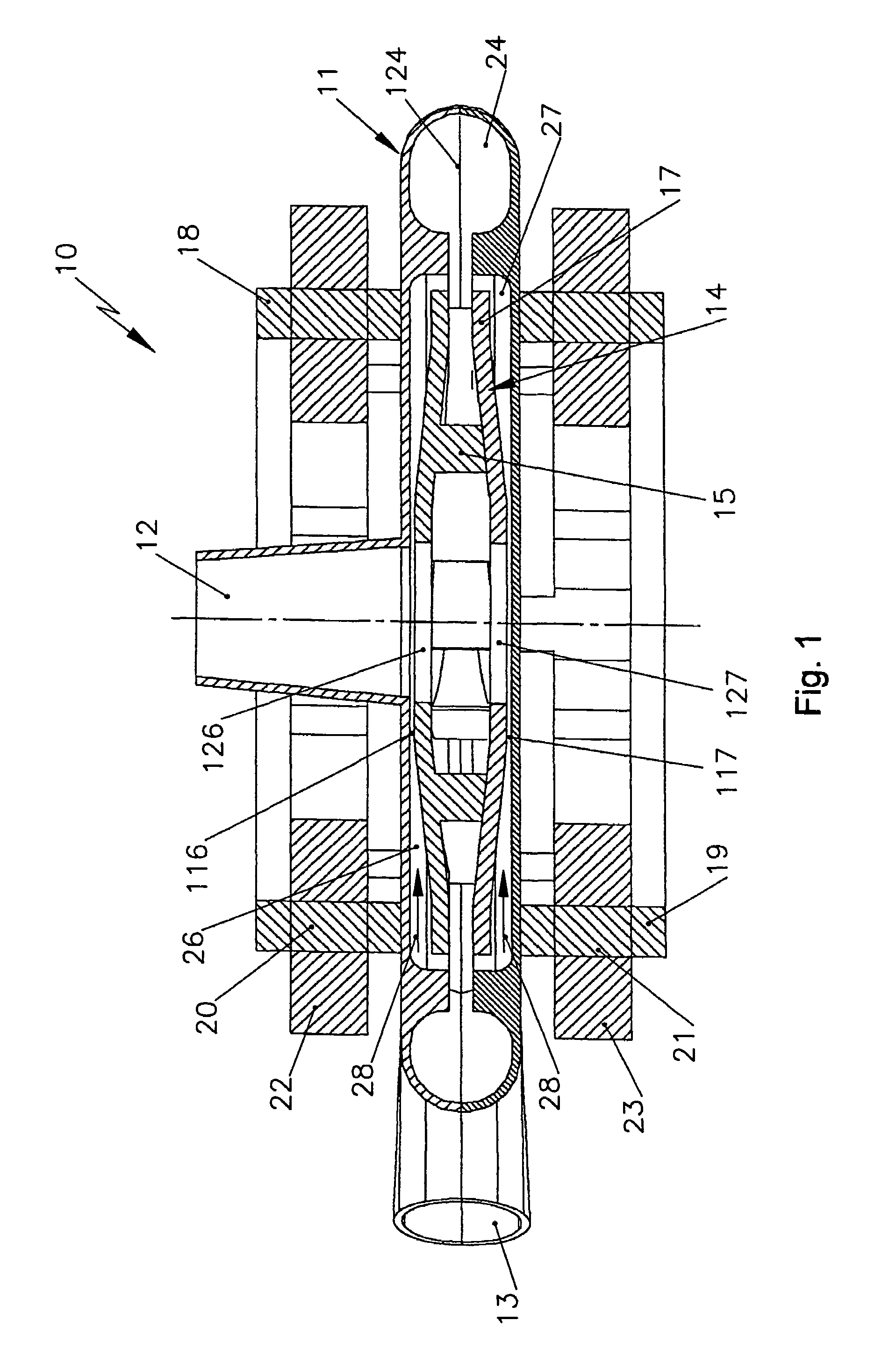
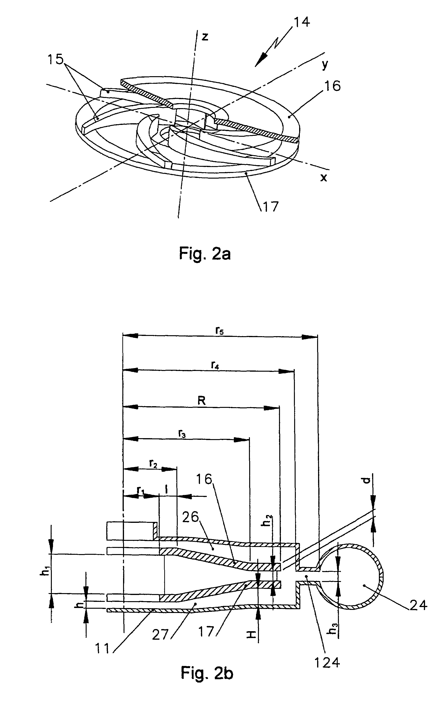
[0049]The centrifugal pump 10 of FIG. 1 has a pump housing 11 with an inlet 12 and a tangential outlet 13 for blood or some other fluid. Otherwise, the pump housing 11 is closed in a fluid- and gas-tight manner. A pump rotor 14 is located in bearingless and rotatable fashion in the interior of the pump housing 11. With the aid of the pump rotor 14, the blood flowing in through the opening 12 is pumped radially outward and toward the outlet 13. To that, the pump rotor has feeder blades 15. The feeder blades 15 are covered at the top and bottom by an upper covering 16 and a lower covering 17.

[0050]The pump rotor 14, at least in its circumferential region, has permanently magnetized regions. In the example shown, however, it is made entirely of a paramagnetic and / or ferromagnetic material. Thus at the same time it forms the rotor for a drive motor, which besides the rotor 14 has two annular stators 18, 19, which have many uniformly distributed portions 20, 21, protruding in the directi...


PUM


Abstract

The invention relates to a centrifugal pump, especially for blood, comprising a pump rotor which is arranged in a rotational manner and without a bearing in a liquid-tight and gas-tight closed housing, except for at least one inlet opening and at least one outlet opening. The rotor is also the rotor of a drive motor. The rotor is symmetrical with respect to the centre plane thereof and comprises an upper and a lower covering. The rotor and / or the pump housing are formed in such a way that the axial distances between the upper and the lower coverings and the upper and lower housing walls are smaller in the radially inner region of the rotor than in the radially outer region. In the radially inner region of the rotor, each lateral rotor chamber comprises a flow-restrictor gap which, when in operation, influences back flows oriented in a radially inward manner in the lateral rotor chambers, such that during an axial deflection of the rotor above and below the rotor, various pressure distributions appear, enabling forces acting upon the predominant surface of the coverings to be produced, the forces bringing about an axial stabilisation of the rotor and acting, in the same manner, against tilting of the rotor inside the housing.

Description

BACKGROUND OF THE INVENTION[0001]The invention relates to a centrifugal pump, in particular for blood in cardiac substitution or assist devices, as generically defined by the preamble to claim 1. In particular, the invention relates to an electrically driven rotary pump of the radial / centrifugal type for permanent implantation in patients with terminal cardiac insufficiency who require mechanical support of their blood circulation.[0002]Blood pumps, especially blood pumps or pumps for other vulnerable fluids, must meet special requirements:[0003]1. High hydraulic efficiency, to keep the heat loss given up to the blood or fluid slight and to keep the energy storing means small.[0004]2. Entirely contactless rotation of the rotor inside a hermetically sealed pump housing, thus precluding any wear, abrasion, and local heat development from mechanical friction.[0005]3. Avoidance of standing eddies and flow stasis zones as well as minimal dwell times of the blood or fluid in the pump, to ...

Claims


Application Information

Patent Timeline
IPC IPC(8): F04B35/04A61M1/10F04D13/06F04D29/04F04D29/048
CPCA61M1/101F04D29/041A61M1/1015F04D13/064F04D29/048F04D29/0413F04D29/0416F04D13/0666A61M60/824A61M60/422A61M60/81A61M60/232A61M60/178A61M60/822A61M60/148
Inventor MENDLER, NIKOLAUS
Owner JOSTRA AG
Learn More