Power supply device and communication system

a power supply device and communication system technology, applied in the direction of liquid/fluent solid measurement, instruments, high-level techniques, etc., can solve the problems of composite machines that consume power to be able to communicate with external devices, composite machines are likely to malfunction, and consume power more than necessary in power-saving operation mod

Inactive Publication Date: 2010-04-13
SHARP KK
View PDF11 Cites 15 Cited by
  • Summary
  • Abstract
  • Description
  • Claims
  • Application Information

AI Technical Summary

Benefits of technology

[0014]Thus, this configuration allows the power supply device to be ready to detect external signal input thereto with minimum power consumption in the power saving operation mode.
[0072]Therefore in the power saving operation mode, power consumption at the communication system is reduced.

Problems solved by technology

The composite machine of Japanese Patent Application Laid-Open No. 2003-63101, however, still consumes power more than necessary in the power-saving operation mode.
The composite machine consumes power to be capable of communicating with external devices in the power-saving operation mode.
Although the composite machine takes some malfunction prevention measures, the composite machine is likely to malfunction when a power-save request and a start-up request are input to the composite machine at about the same time with a slight time lug, or when noise are added to a power-save request to be input to the composite machine.

Method used


Image

  • Power supply device and communication system
  • Power supply device and communication system
  • Power supply device and communication system

Examples


first embodiment

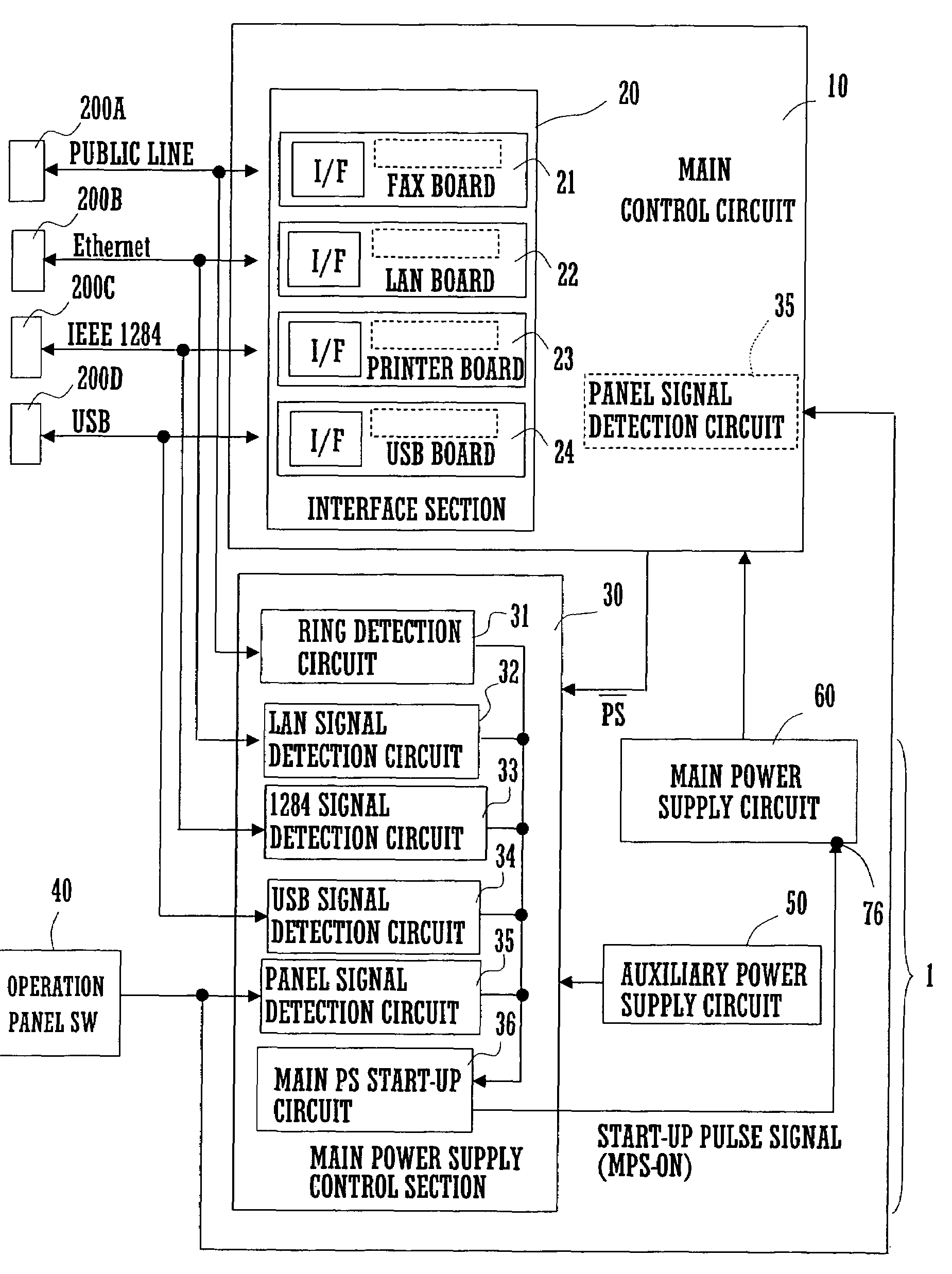
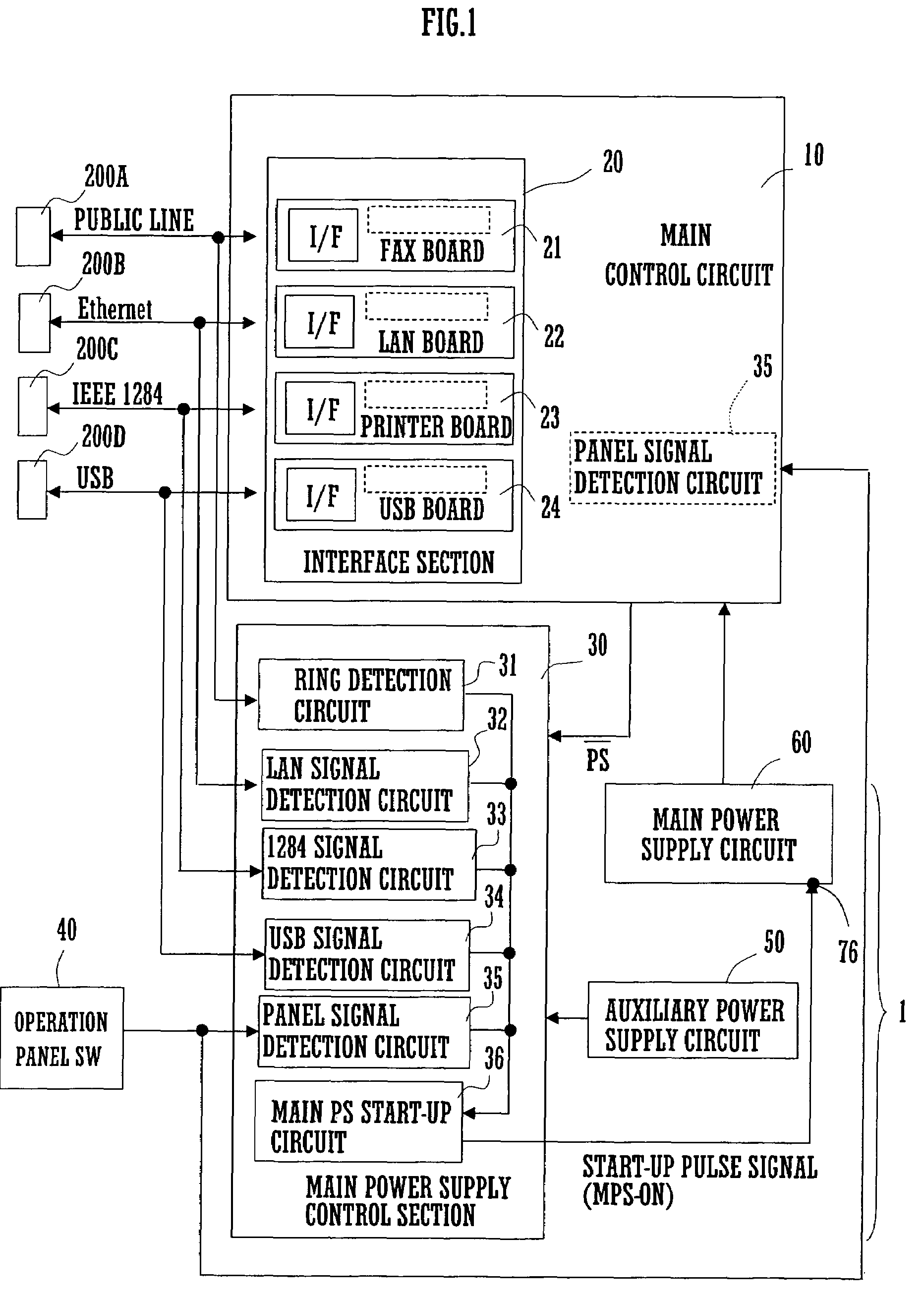
[0093]FIG. 1 is a block diagram illustrating a configuration of a power supply device 1 and a communication system according to the present invention. As shown in FIG. 1, the communication system includes a power supply device 1, external devices 200A to 200D, and MFP. The MFP has a main control circuit 10, the power supply device 1, and an operation panel switch 40. The power supply device 1 has a main power supply control section 30, an auxiliary power supply circuit 50, a main power supply circuit 60.

[0094]The main control circuit 10 is a main controller of MFP. The main control circuit 10 includes an interface section 20 that is utilized for communication between the MFP and external devices 200A to 200D connected to the MFP. The main control circuit 10 outputs a PS signal with low level value to the main power supply control section 30, when stopping operation of the main power supply circuit 60.

[0095]The interface section 20 has a FAX board 21, a LAN board 22, a printer board ...

third embodiment

[0129]FIG. 10 illustrates a configuration of a FAX board 21 that has an external telephone additionally connected to a telephone line through a normally closed (or N.C.) relay contact 81. The MFP in the third embodiment decides that a power-save request or a start-up request is valid when the MFP confirms that the power-save request or the start-up request has been continued for a predetermined period of time. This is because decision based on detection of an edge of a power-save signal or a start-up request signal may result in false detection of such signal if the signal is overlapped with a noise.

[0130]FIG. 11 is a flowchart of a start-up process according to the third embodiment, performed by the main power supply control section 30. First, a count variable N for counting a period of time during which a start-up request is continued is cleared (step S1). The main power supply control section 30 is then held on standby until a start-up request is made (step S2).

[0131]When a start...


PUM


Abstract

The invention relates to a power supply device and a communication system. The power supply device supplies power to a main device. The communication system is provided with the main device mounting the power supply device therein and an external device connected to the main device. A feature of the invention is to offer a power supply device and a communication system that are capable of being responsive to external signals for returning to a normal operation mode with minimum power consumption in a power-saving operation mode. In the power saving operation mode, a main power supply circuit (60) is turned off and only an auxiliary power supply circuit (50) is operated. In order to detect external signal, the auxiliary power supply circuit (50) supplies power not to an entire interface section (20), but to a ring detection circuit (31), a LAN signal detection circuit (32), a 1284 signal detection circuit (33), a USB signal detection circuit (34), and a panel signal detection circuit (35) that are respectively provided with a minimum functions for detecting external signal.

Description

FIELD OF THE INVENTION[0001]The present invention relates to a power supply device that supplies power to an electrical appliance such as a personal computer and an image forming apparatus, and to a communication system provided with the power supply device.BACKGROUND OF THE INVENTION[0002]In electrical appliance such as personal computer and image forming apparatus, attention has been focused on reducing standby power consumption to a minimum level. One known solution is to incorporate a power supply device that stops power supply from a main power supply circuit during standby time.[0003]However, an electrical appliance on standby is sometimes required to return to a normal operation mode in response to external signals. During standby time, a facsimile, for example, needs to be ready to appropriately receive facsimile data input externally over telephone lines. A printer needs to return to a normal operation state immediately on detection of image data input from a personal compu...

Claims


Application Information

Patent Timeline
Patent Type & Authority Patents(United States)
IPC IPC(8): G06F1/32B41J29/393
CPCB41J29/393G06F1/3209G06F1/3287Y02B60/1278Y02B60/32Y02B60/1282Y02D10/00Y02D30/50
Inventor MORIMOTO, KENICHINISHIMOTO, YOSHIOIWABAYASHI, KAZUYAMAITANI, YOSHIFUMINAGANO, YUSUKE
Owner SHARP KK
Why Eureka
Try Eureka