Electric double layer capacitor with a sealing plate fitted inside a container
a technology of sealing plate and capacitor, which is applied in the directions of casing/cabinet/drawer details, electrical equipment casings/cabinets/drawers, transportation and packaging, etc. it can solve the problems of high cost of parts and manufacturing, dead space tends to exist when mounting, and parts cannot be mounted on printed circuit boards with high density, so as to reduce the displacement of sealing plate in the horizontal direction, prevent the effect of yield declin
- Summary
- Abstract
- Description
- Claims
- Application Information
AI Technical Summary
Benefits of technology
Problems solved by technology
Method used
Image
Examples
first example
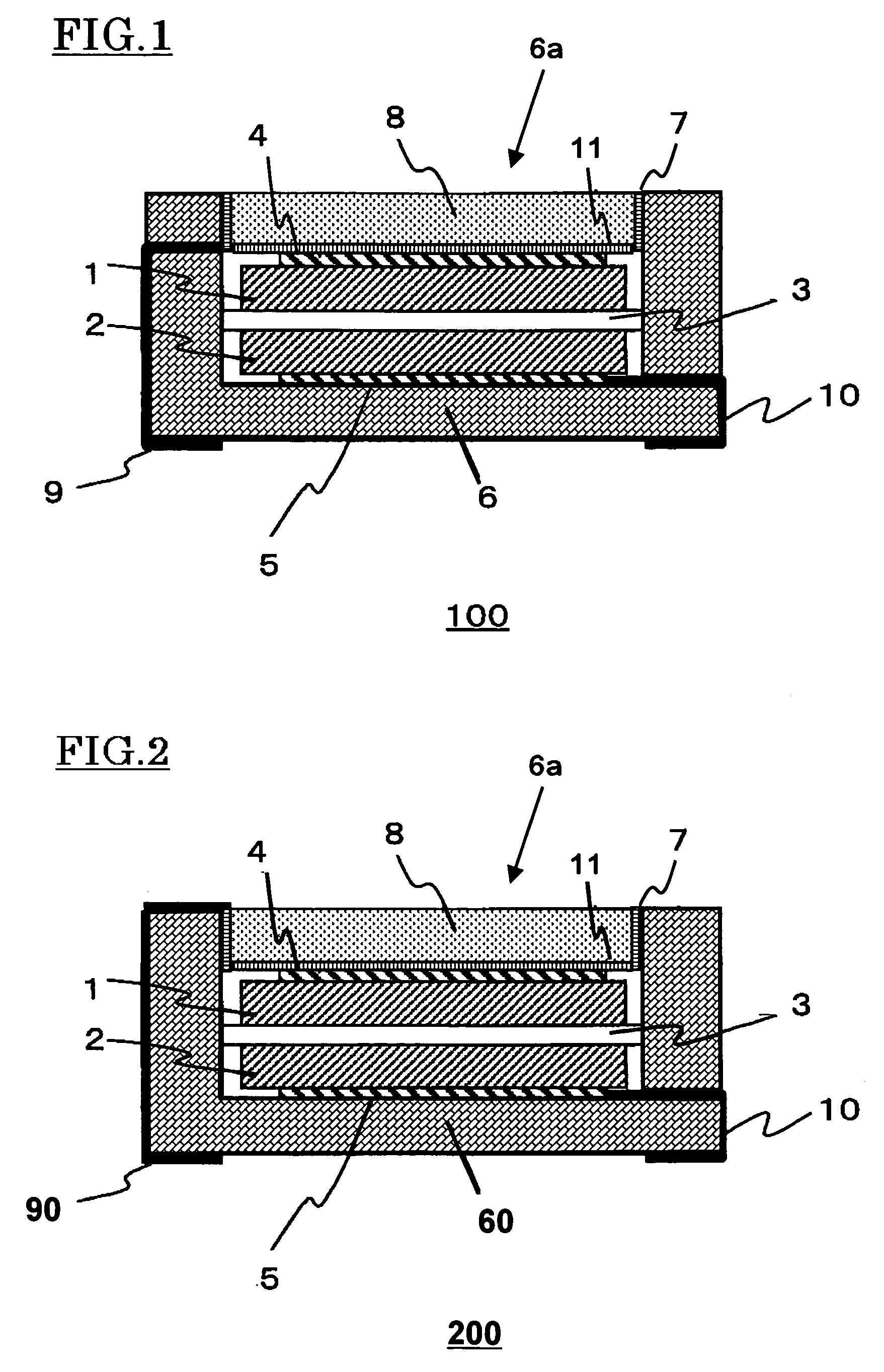
[0027]FIG. 1 shows the structure of the electric double layer capacitor 100 of the first example. Here, 1 is a first electrode, 2 is a second electrode, 3 is a separator, 4 is a first current collector, 5 is a second current collector, 6 is a concave-shaped container, 6a is an containing space, 7 is a first metal layer, 8 is a sealing plate, 9 is a first external connecting terminal, 10 is a second external connecting terminal, and 11 is a second metal layer.
[0028]The concave-shaped container 6 is a frame object made from alumina, having a square shaped undersurface of 5 mm on each side, and height of 1.6 mm. On the upper surface side of the container 6, a concave shaped containing space 6a having 3.6 mm on each side square and depth of 1.4 mm is formed. On the bottom part of the unit 6a, the current collector 5, where gold is coated on tungsten, is formed.
[0029]On an undersurface of a bottom wall portion and on an external surface of the side wall portion of the concave-shaped cont...
second example
[0037]As shown in FIG. 2, in an electric double layer capacitor 200 of the second example, a first external connecting terminal 90 is formed along the external surface of the concave-shaped container 60 from the bottom end to the upper end, and the first external connecting terminal 90 is extended to the internal surface of the concave-shaped container 60 along an edge part of the opening part. This is an alternative to the first external connecting terminal 9 of the capacitor 100 in the first example which penetrated through the side wall portion of the concave-shaped container 6. A first metal layer 7, which is on an internal surface of the containing space 6a, is formed so that it can cover the first external connecting terminal 90. Except the above, the capacitor 200 of the second example has same configurations as the capacitor 100, and the same numbers are attached in the figure for the same configurations.
[0038]According to the present example, by having a structure fitting t...
third example
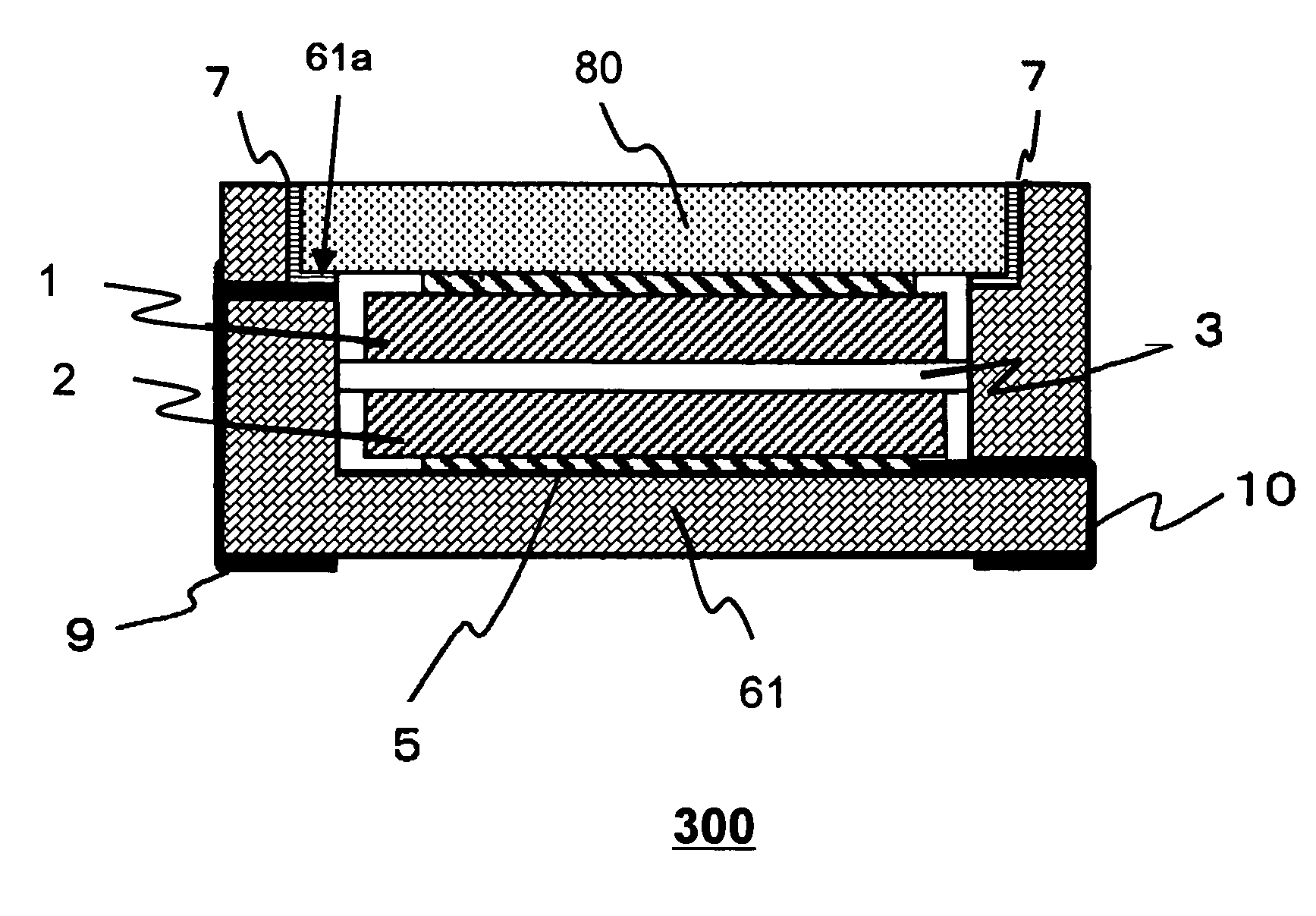
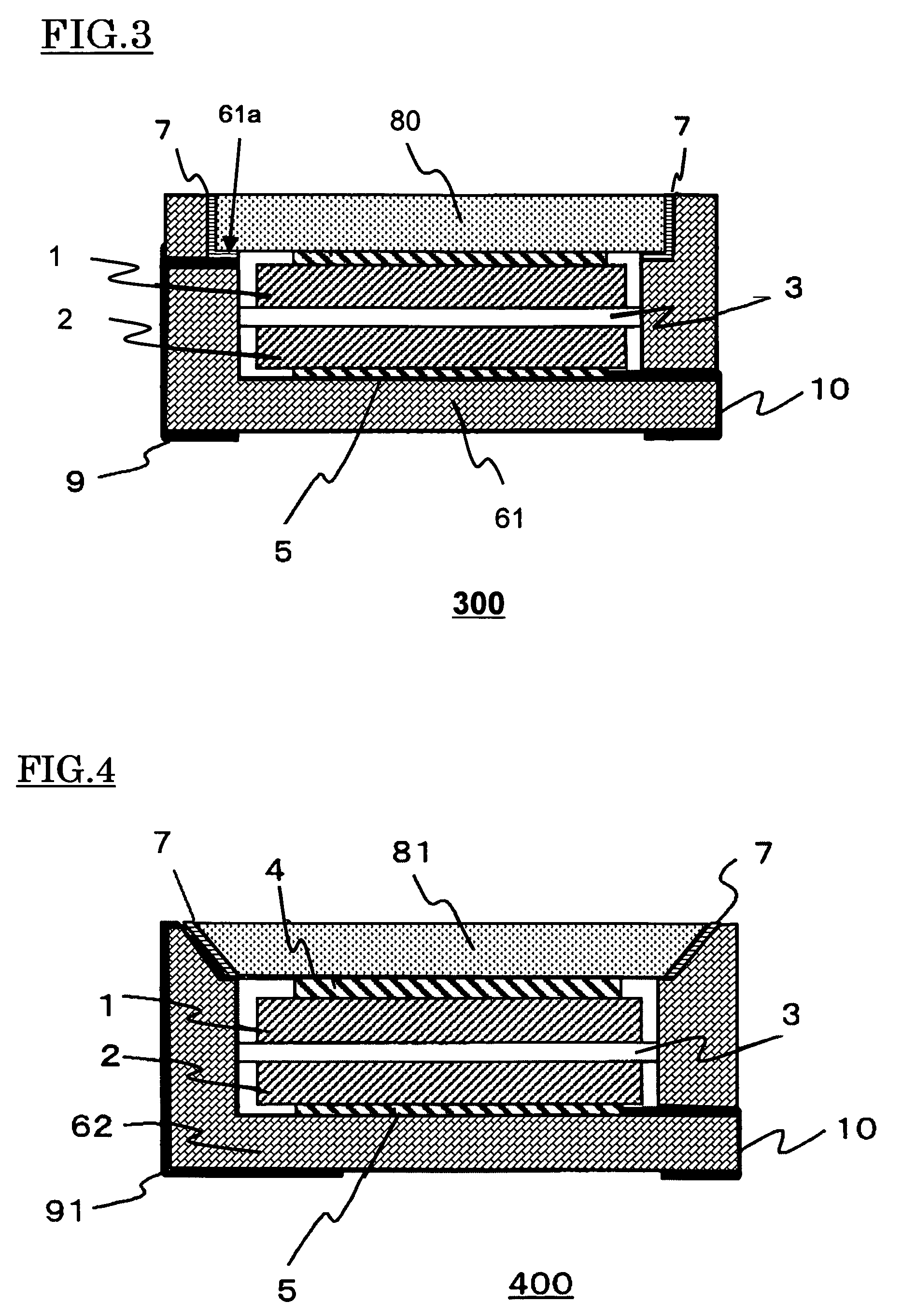
[0039]As shown in FIG. 3, in the electric double layer capacitor 300 of the third example, a level difference part 61a forms an internal surface of the concave-shaped container 61. In other words, the containing space of the container 61 has a lower containing space having a square shaped surface of 3.6 mm on each side and 1.1 mm depth and an upper containing space having a square shaped surface of 4 mm on each side and 0.3 mm depth. When viewing the part 61a from the upper surface side, the part 61a looks like a square strip shaped object, where the width of the strip is 0.2 mm. The external connecting terminal 9, which penetrates through the side wall of the container 61, is formed extending to the part 61a. The external connecting terminal 9 may be extended to an inner edge part of the level difference part 61a. The first metal layer 7 is formed on an area contacting with a sealing plate 80 when sealing to the internal surface of the container 61 and on the part 61a. The first me...
PUM
 Abstract
Description
Claims
Application Information
 - R&D
- Intellectual Property
- Life Sciences
- Materials
- Tech Scout
- Unparalleled Data Quality
- Higher Quality Content
- 60% Fewer Hallucinations
Browse by: Latest US Patents, China's latest patents, Technical Efficacy Thesaurus, Application Domain, Technology Topic, Popular Technical Reports.
© 2025 PatSnap. All rights reserved.Legal|Privacy policy|Modern Slavery Act Transparency Statement|Sitemap|About US| Contact US: help@patsnap.com


