
Lighting device and observation device

a technology of observation device and light source, which is applied in the field of light source device, can solve the problems of insufficient presentation of capsule membrane, inhomogeneity of red reflex, and deterioration of homogeneity, and achieve the effect of reducing the expenditure of optical components

Active Publication Date: 2010-04-13
CARL ZEISS SURGICAL
View PDF11 Cites 4 Cited by
  • Summary
  • Abstract
  • Description
  • Claims
  • Application Information

AI Technical Summary

Benefits of technology

[0019]This object is solved according to the invention by the lighting device with the features according to the independent patent claim 1, the observation device with the features according to the independent patent claim 11, as well as the particular uses according to the independent patent claim 5. Other advantages, features, details, aspects and effects of the invention result from the subclaims, the description, as well as the drawings. Features and details, which are described in connection with the lighting device according to the invention, thus also apply, obviously, in connection with the observation device according to the invention and vice versa. The same is true for the particular uses.
[0020]The essence of the solution according to the invention thus first lies in a new conception of the lighting device. The present invention is thus based on the knowledge that the solution to the object according to the invention is provided by the well-defined interaction between the observation beam path and a newly conceived—at least in part—lighting beam path, and in fact with very specific optical imaging properties of the interwoven beam path of the luminous-field image and pupil mapping, thus in this case, the imaging of the light source.
[0021]A basic prerequisite for this interaction consists of the fact that relative to the optical imaging properties of the lighting beam path, substantially higher requirements must be placed on correction conditions for optical imaging errors (aberrations) that occur than is generally common in the case of conventional lighting devices.
[0022]As will be illustrated further below, with respect to the lighting device, this basic requirement can be achieved with minimal expenditure for optical components.
[0023]According to the first aspect of the invention, a lighting device is provided for an observation device, in particular for an operating microscope, with a light source and with optical components, which are provided between the light source and an objective element. The lighting device is characterized according to the invention in that the optical components are structured and arranged in such a way that the mapping of the lighting pupil is produced on the fundus of the object to be observed.
[0024]A virtual image is formed for the mapping of the lighting pupil in front of the object to be observed, thus in front of the eye of the patient. The position of this virtual image corresponds to the conjugated image site of the fundus, and thus varies with the refractive error of the eye. In particular, this virtual image then lies at the far point of the eye for an eye with correct vision.

Problems solved by technology

The second fundamental requirement also described above of a good contrasting of the lens pieces in the lens capsule and the presentation of the capsule membrane is not sufficiently fulfilled, however, by the known lighting systems with zero-degree illumination.
Due to the angle which varies in magnitude between the observation axis and the lighting axis, however, a shading of the red reflex that is of variable intensity is obtained, thus the disadvantage of an inhomogeneity of the red reflex.
As a consequence, the advantage of an improved contrasting leads to a deterioration in homogeneity.
The proposed solutions known from the prior art all have the disadvantage that the requirements relative to homogeneity and contrasting cannot be fulfilled simultaneously as a consequence of the inconsistencies that necessarily occur.

Method used


Image

  • Lighting device and observation device
  • Lighting device and observation device
  • Lighting device and observation device

Examples


Embodiment Construction

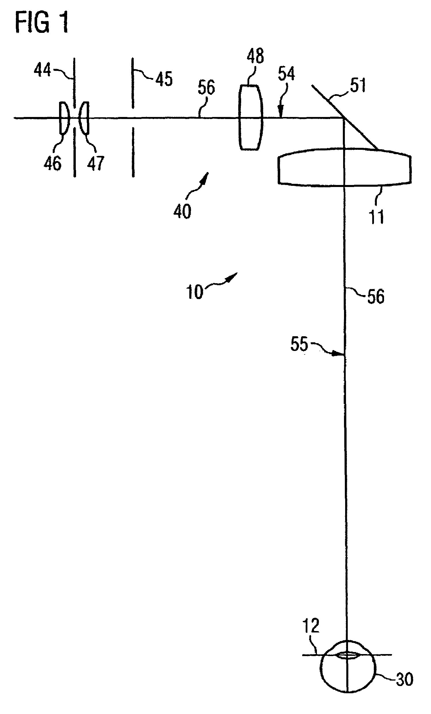
[0069]A lighting device 40, which is a component of an observation device 10, is shown in FIGS. 1 and 2. The observation device 10 involves an ophthalmologic stereo operating microscope, which is utilized for a special application in eye surgery, i.e., cataract surgery. The lighting device 40, which is explained in more detail in the following, has a light source 41, which is formed in the present example as a fiber-optic light guide. In addition, an objective element 11 is provided, which in the present case is also the principal objective of the observation device 10. A number of optical components are provided between light guide 41 and the principal objective 11. The object plane 12 of the object 30 to be investigated is formed in the front focal point of the principal objective 11. The object 30 to be investigated involves an eye.

[0070]For purposes of simulation, eye 30 is formed as a so-called “model eye”. Experience for many years has shown that an aphacic (with defect of the...


PUM


Abstract

A lighting device (40) is described for an observation device (10), in particular for an ophthalmologic operating microscope, as well as such an observation device (10). The lighting device (40) has a light source (41) as well as a number of optical components, which are provided between light source (41) and an objective element (11). The optical components are designed according to the invention in such a way that the imaging of the lighting pupil (43) and the observation pupils is produced on the fundus of the eye (30). In this way, an exactly defined interaction of the lighting beam path (56) with an observation beam path is made possible, whereby practical requirements can be fulfilled relative to the homogeneity of the red reflex with simultaneous sufficiently good contrasting.

Description

BACKGROUND OF THE INVENTION[0001]The present invention relates to a lighting device for an observation device and to an observation device.[0002]For example, an observation device may involve an operating microscope. In particular, the observation device can be designed as an ophthalmologic operating microscope, which is utilized, for example, for a special application in eye surgery, i.e., cataract surgery.[0003]In the case of cataract surgery, a lens of the eye—which is clouded, for example, due to the cataract—is replaced by an artificial lens.[0004]The lens of an eye is found inside a thin envelope, the so-called lens capsule. In order to remove the lens, access to it is created to it by a thin cut made in the lens capsule and the lens is next broken up into small pieces with a microsurgical instrument, and then these pieces are removed by means of an aspirating device.[0005]This process takes place under microscopic observation—for example, under stereomicroscopic observation—e...

Claims


Application Information

Patent Timeline
Patent Type & Authority Patents(United States)
IPC IPC(8): G02B21/06A61B3/13A61B90/20G02B13/00
CPCA61B3/13A61B19/5223A61B19/5202A61B90/30A61B90/20
Inventor REIMER, PETERSTRAEHLE, FRITZKOLSTER, DANIEL
Owner CARL ZEISS SURGICAL
Learn More