
Suction cup

a technology of suction cup and suction cup, which is applied in the field of suction cup, can solve the problems of forming a gap between the adsorption surface and the surface to be adsorbed, the limit the difficulty of ensuring the adhesiveness of the suction cup, so as to ensure the adhesiveness of the adsorption surfa

Inactive Publication Date: 2010-04-06
SONY CORP
View PDF24 Cites 21 Cited by
  • Summary
  • Abstract
  • Description
  • Claims
  • Application Information

AI Technical Summary

Benefits of technology

The suction cup maintains adhesiveness for an extended period, as demonstrated by a 60-day adsorption maintenance time on leather-like creped surfaces, compared to 15-30 days with conventional designs, while reducing material usage and costs.

Problems solved by technology

If the surface to be adsorbed is such as having fine irregularity or roughness, typically as found in dashboards of automobiles, any effort of allowing the adsorption surface of the suction cup to adsorb the surface to be adsorbed fails in keeping adhesiveness between the adsorption surface and the surface to be adsorbed, resulting in formation of a gap between the adsorption surface and the surface to be adsorbed.
As a consequence, air comes through the gap to reach the adsorption surface, making it difficult to ensure the adhesiveness by the suction cup.
Even the suction cup using the above-described soft material, however, cannot keep close adhesiveness between the adsorption surface and the surface to be adsorbed, if the surface to be adsorbed has an irregular surface or roughened surface, placing a limit of ensuring adhesiveness of the suction cup.

Method used


Image

  • Suction cup
  • Suction cup
  • Suction cup

Examples


Embodiment Construction

[0020]Embodiments of the present invention will be explained referring to the attached drawings.

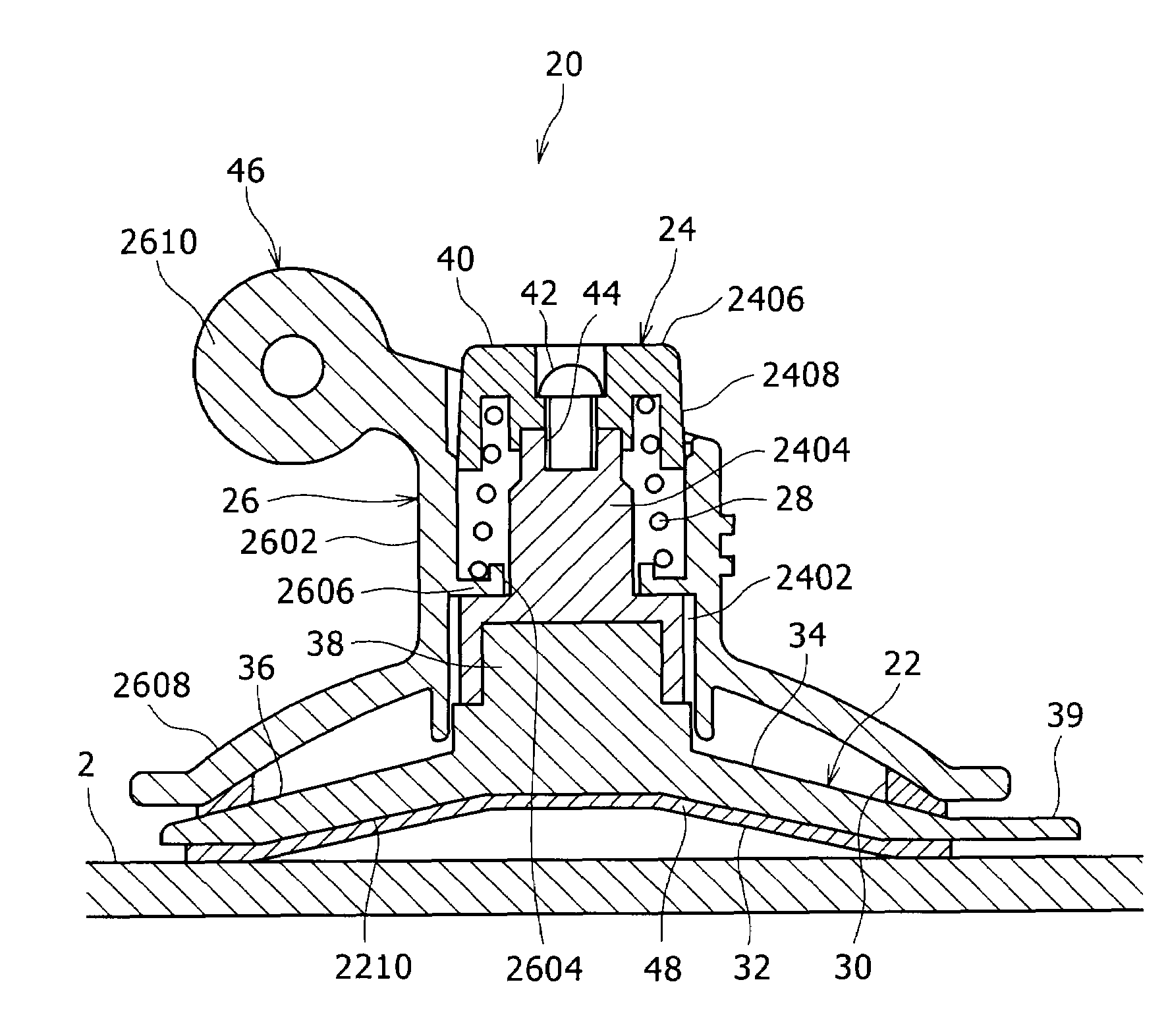
[0021]Paragraphs below will explain a case where a display of a car navigation system as a car-borne instrument is attached to a dashboard, front panel and so forth, with the aid of the suction cup device 20 using the suction cup of the present invention.

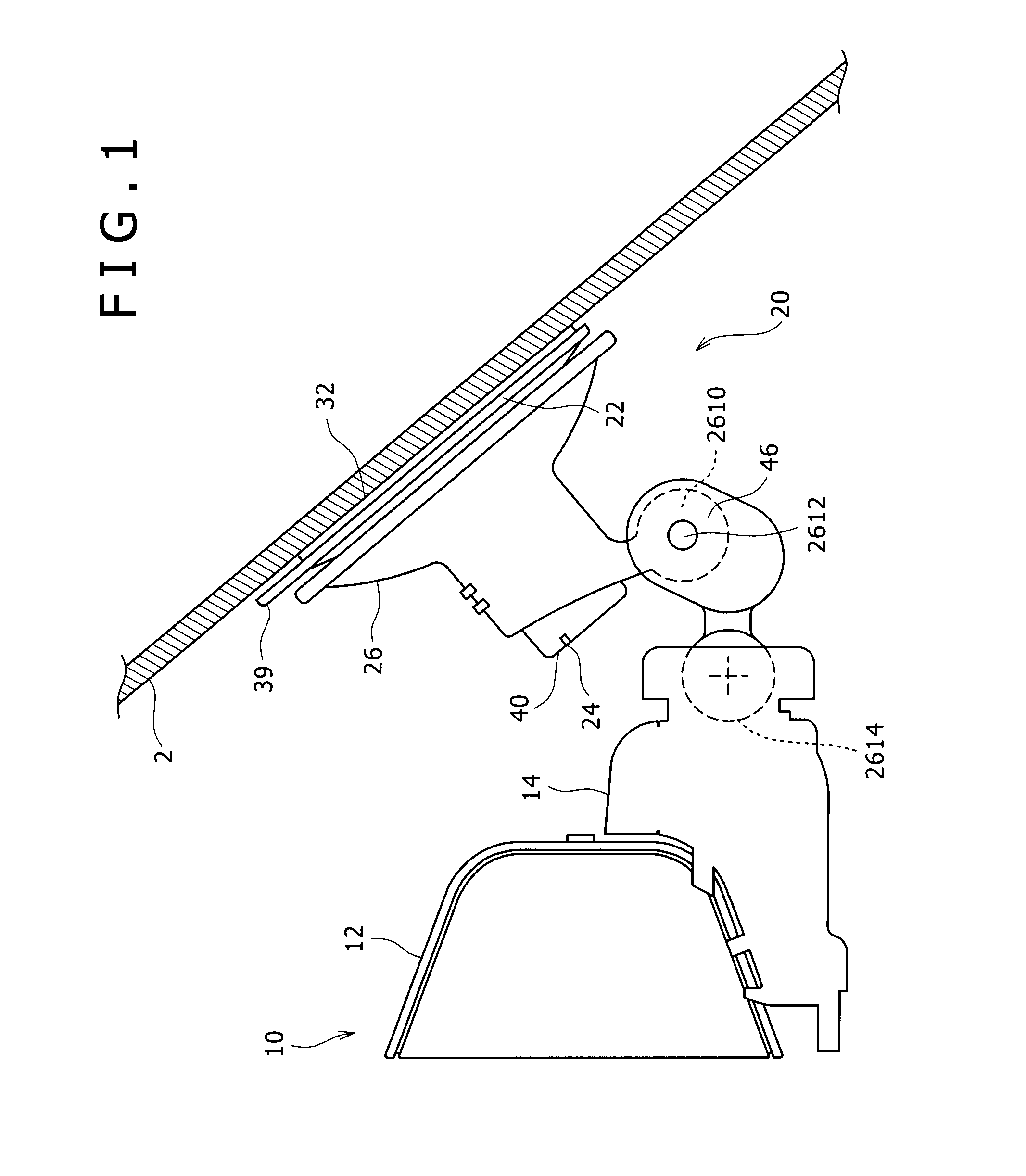
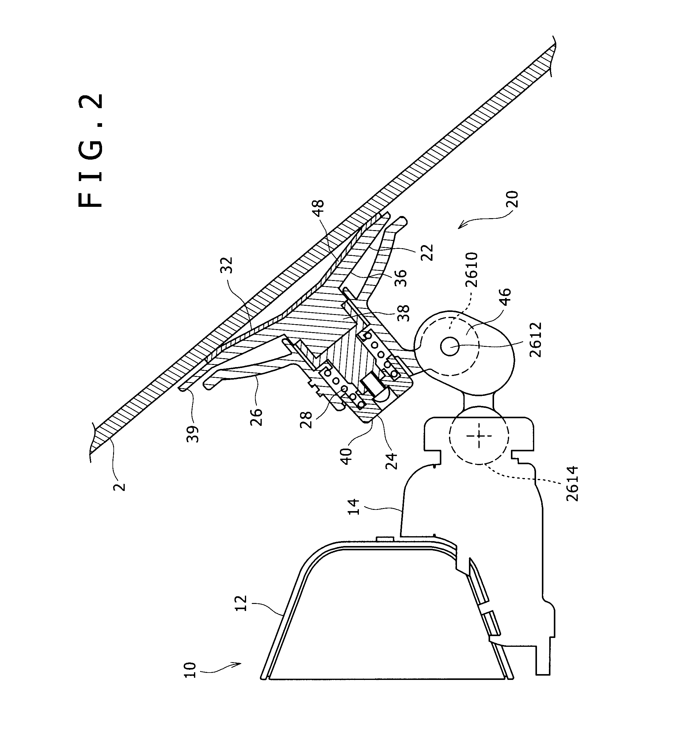
[0022]FIG. 1 is a side elevation of a state of attachment of a display of a car navigation system to a dashboard or a front glass panel, with the aid of the suction cup device 20, and FIG. 2 is a sectional view of FIG. 1.

[0023]As shown in FIGS. 1 and 2, a holder 14 is provided on the back surface of a frame 12 of a display 10 of a car navigation system as being projected out therefrom, a suction cup device 20 is provided behind the holder 14, and the suction cup device 20 is attached to the surface to be adsorbed 2, such as a dashboard, front glass panel or the like.

[0024]The surface to be adsorbed 2, given as the dashboard, is inclined t...


PUM


Abstract

A suction cup having an adsorption surface is provided wherein the suction cup has a disk-like main suction cup unit composed of an elastically-deformable material and has an attachment surface. The attachment surface has a gel layer composed of a gel, bonded thereto so as to cover the attachment surface. The adsorption surface is formed by the surface of the gel layer, and the gel layer are composed of a center portion composing the center of the adsorption surface, and a circumferential portion composing the outer circumference of the adsorption surface. The outer circumferential portion has the thickness larger than the thickness of the center portion.

Description

BACKGROUND OF THE INVENTION[0001]1. Field of the Invention[0002]The present invention relates to a suction cup.[0003]2. Description of the Related Art[0004]Suction cup is used for the purpose of attaching various objects to surfaces to be adsorbed.[0005]If the surface to be adsorbed is such as having fine irregularity or roughness, typically as found in dashboards of automobiles, any effort of allowing the adsorption surface of the suction cup to adsorb the surface to be adsorbed fails in keeping adhesiveness between the adsorption surface and the surface to be adsorbed, resulting in formation of a gap between the adsorption surface and the surface to be adsorbed. As a consequence, air comes through the gap to reach the adsorption surface, making it difficult to ensure the adhesiveness by the suction cup.[0006]There has been proposed a suction cup, having a main suction cup unit formed using a hard material such as hard rubber or hard synthetic resin, and a soft material such as sof...

Claims


Application Information

Patent Timeline
Patent Type & Authority Patents(United States)
IPC IPC(8): A45D42/14
CPCF16B47/00
Inventor AKAI, TAKAYUKIKAWABATA, MAKOTO
Owner SONY CORP
Learn More