
Power of two multiplication engine

a multiplication engine and power technology, applied in computing, computation using denominational number representation, instruments, etc., can solve the problems of high hardware and hardware consumption, high overhead, and inconvenient operation, and achieve efficient implementation, efficient implementation, and minimum storage and execution overhead

Inactive Publication Date: 2010-03-23
SONY CORP +1
View PDF8 Cites 0 Cited by
  • Summary
  • Abstract
  • Description
  • Claims
  • Application Information

AI Technical Summary

Benefits of technology

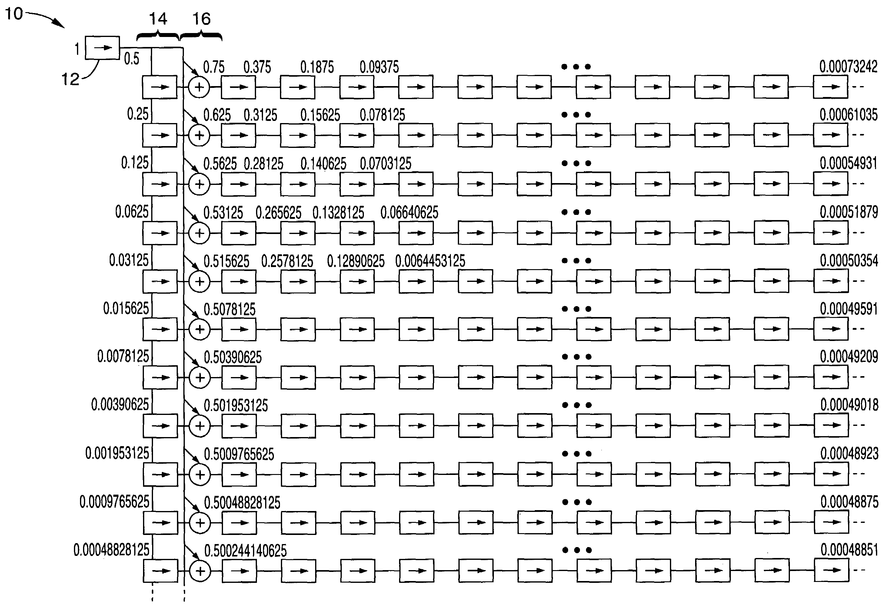
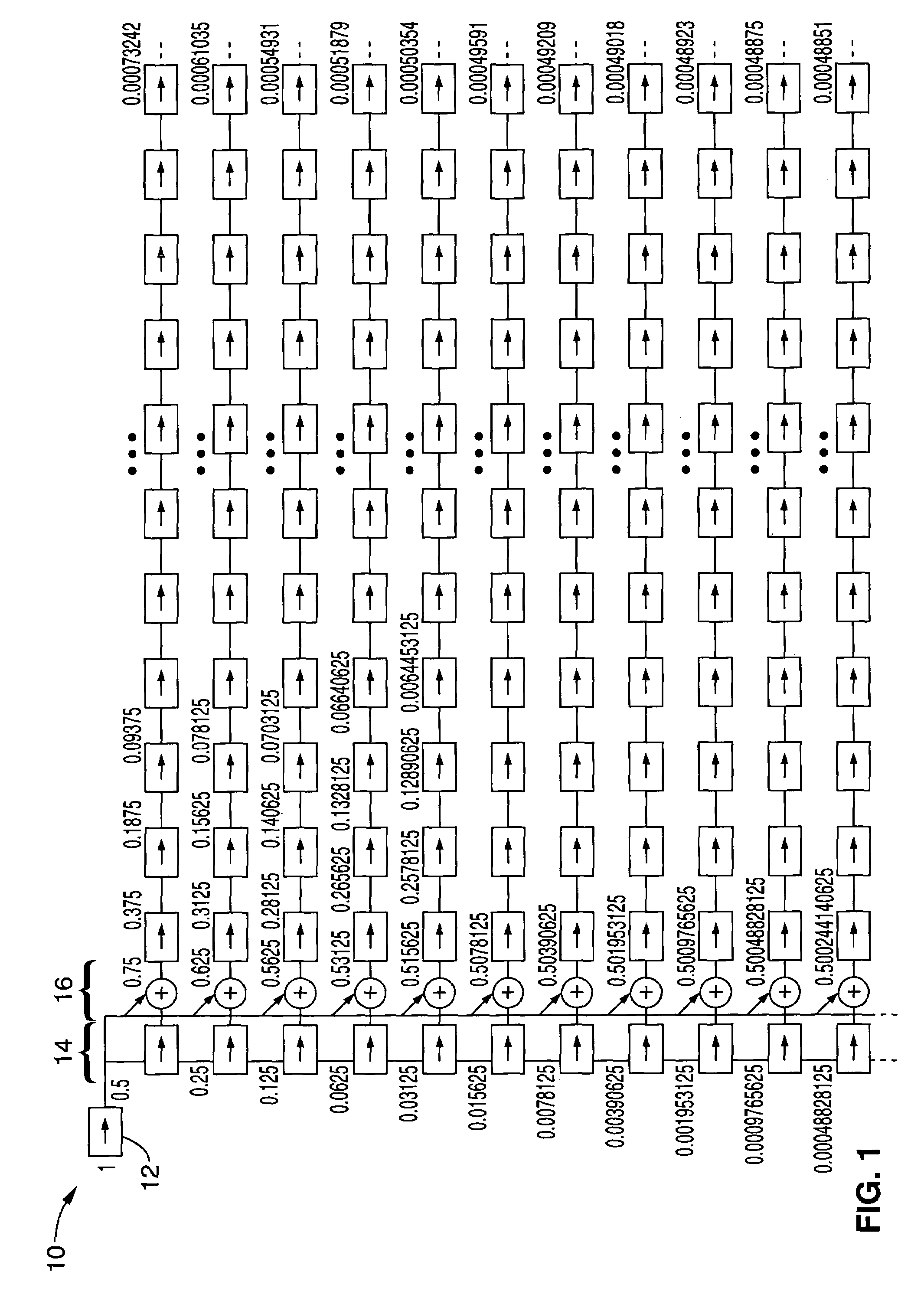
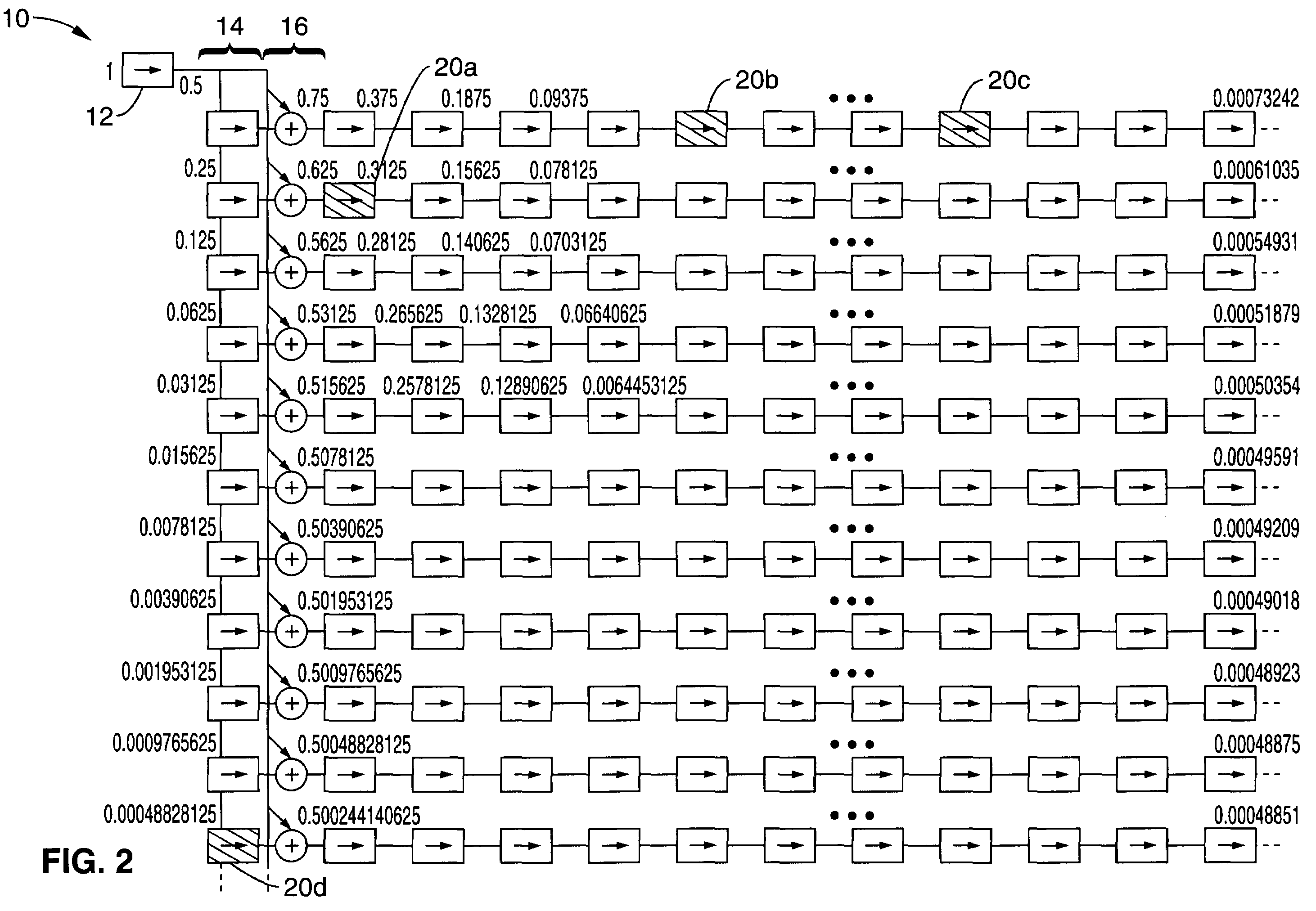
The present invention is a method and apparatus for performing a rapid and low-overhead power of two multiplication in electronic circuits. The method involves creating a Y-adder power of two shift table with a multiplicand input of a desired bit width and a column of adders and shifters. The shift-add paths in the table are then determined based on the desired multiplier value and the coefficients of the multiplication. The apparatus includes hardware components such as slide shifters and adders, which can be set into an active state or a passive state. The invention can be implemented in hardware, firmware, or software, and can be used in static or dynamic multiplication. The technical effects of the invention include high speed and accuracy in performing power of two multiplication, as well as flexibility in selecting different multipliers without reconnecting shift and add paths.

Problems solved by technology

Implementation of multipliers typically requires a substantial amount of hardware, especially if many bits of accuracy are required.
For signal processing applications that encompass changing coefficients, the typical implementation utilizes a dedicated multiplier, which is hardware intensive and as a result costly.

Method used


Image

  • Power of two multiplication engine
  • Power of two multiplication engine
  • Power of two multiplication engine

Examples


embodiment 26

[0114]FIG. 3 illustrates the combined shift and add paths from the table associated with the located coefficients for the example multiplier value of ⅓. Data input 28 connects to shifters 32b-32g and to adders 34a-34e to generate data output 30. It can be seen that this technique allows for the rapid development of hardware which performs multiplications, or in which multiplications are integrated. It should be noted that multiple sequential shifts are shown with a binary power notation, such as block 32d which is 2−9 representing 9 right shifts, block 32f which is 2−5 representing 5 right shift, and block 32g which is 2−3 representing three right shift.

[0115]The combination of shift and add paths for the example multiplication by ⅓ will result in multiplying the data by 0.333251953125. As part of the testing of the present technique we confirmed the operation of this static coefficient example within an FPGA design. Several filters were also made using this engine having various nu...

embodiment 90

[0140]FIG. 8 illustrates an embodiment 90 of a multiplier engine that is implemented completely in hardware and operates without need of reconfiguring connections between the shifters and adders to perform the multiplication. This embodiment is referred to as a “Y-adder slide shifter multiplication engine” and it can execute multiplications with any multiplier value (within the range of the associated table construct) rapidly as the multiplication is performed in hardware and can be readily setup for separate multiplier values. It should be appreciated that aspects described in the following embodiment can be applied separately or in any desired combination with aspects previously described without departing from the teachings of the present invention.

[0141]The hardware table implementation utilizes selectable operation blocks to form the table, so that the connections between shifters need not be changed. In the following embodiment each shifter and adder can be set by the controll...


PUM


Abstract

A multiplication engine is described in which a decision threshold engine utilizes a Y-adder powers of two shift table to iteratively generate shift-add combinations. The shift-add combinations are output in a sequence with decreasing levels of contribution wherein the accuracy of the associated multiplication increases up to any desired level of accuracy to meet the requirements of the application. The multiplication engine can be used for generating the combinations either statically or dynamically. One embodiment describes a Y-adder hardware slider table engine in which the shift table is implemented with shifters and adders that can be set for active state or pass through state, and selectively summed to generate a product result directly from the table without the need to combine shift and add hardware.

Description

CROSS-REFERENCE TO RELATED APPLICATIONS[0001]This application claims priority from U.S. provisional application Ser. No. 60 / 624,461, filed on Nov. 1, 2004, incorporated herein by reference in its entirety.STATEMENT REGARDING FEDERALLY SPONSORED RESEARCH OR DEVELOPMENT[0002]Not ApplicableNOTICE OF MATERIAL SUBJECT TO COPYRIGHT PROTECTION[0003]A portion of the material in this patent document is subject to copyright protection under the copyright laws of the United States and of other countries. The owner of the copyright rights has no objection to the facsimile reproduction by anyone of the patent document or the patent disclosure, as it appears in the United States Patent and Trademark Office publicly available file or records, but otherwise reserves all copyright rights whatsoever. The copyright owner does not hereby waive any of its rights to have this patent document maintained in secrecy, including without limitation its rights pursuant to 37 C.F.R. § 1.14.BACKGROUND OF THE INVE...

Claims


Application Information

Patent Timeline
Patent Type & Authority Patents(United States)
IPC IPC(8): G06F7/53
CPCG06F7/523G06F7/535
Inventor FAY, LUKE
Owner SONY CORP
Learn More