Plasma display panel with improved barrier ribs
a technology of barrier ribs and display panels, which is applied in the direction of discharge tubes/lamp details, gas-filled discharge tubes, incadescent body mounting/support, etc., can solve the problems of reducing the adhesion density of the substrate, generating noise in the panel, and failure of crosstalk, so as to save the manufacturing process of forming sbr and cost accordingly
- Summary
- Abstract
- Description
- Claims
- Application Information
AI Technical Summary
Benefits of technology
Problems solved by technology
Method used
Image
Examples
first embodiment
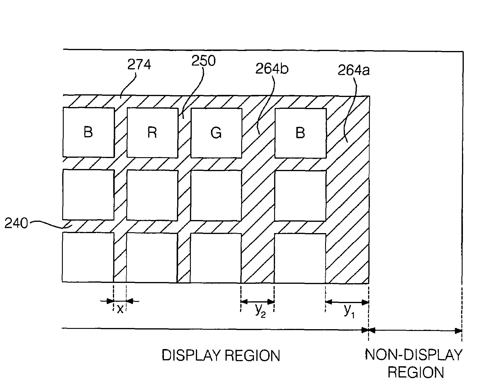
[0045]FIG. 5 is a plan view of the rear substrate taken along line A-A′ in the plasma display panel shown in FIG. 4. A barrier rib structure of the first embodiment will be described with reference to FIG. 5. In FIG. 5, a hatched portion indicates a plan view of a top surface of the barrier ribs.
[0046]In the first embodiment, barrier ribs 240, 250, 260 and 270 that partition discharge spaces are formed on the rear substrate within the display region.
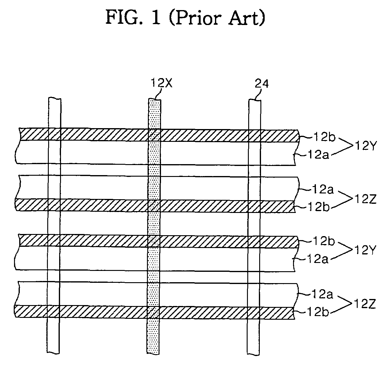
[0047]In this case, the barrier ribs located within the outer block of the display region will be referred to as the inner barrier ribs 240, 250. The barrier ribs located in the outer block will be referred to as the outer barrier ribs 260, 270. Furthermore, in the inner barrier ribs 240, 250 and the outer barrier ribs 260, 270, barrier ribs formed parallel to the scan electrodes 12Y and the sustain electrodes 12Z shown in FIG. 1 will be referred to as the traverse inner barrier ribs 240 and the traverse outer barrier ribs 270. Barrier r...
second embodiment
[0059]Therefore, in the second embodiment, the width (z) of the traverse inner barrier ribs 240 can be set in the range of approximately 30 to 60 μm and a width (r) of the traverse outer barrier rib 271 can be set in the range of approximately 45 to 30000 μm.
[0060]That is, the width (r) of the traverse outer barrier rib 271 is set to be 1.5 to 200 times sufficiently wider than the width (z) of the traverse inner barrier ribs 240, so that it can bear pressure applied when the substrates are combined.
[0061]Therefore, the plurality of longitudinal inner barrier ribs 250 and the longitudinal outer barrier ribs 261 have substantially the same width, and the traverse inner barrier ribs 240 also have substantially the same width.
[0062]Meanwhile, in the second embodiment, the traverse outer barrier rib 271 is a barrier rib located on an upper side of the rear substrate and has the same width as that of a traverse outer barrier rib (not shown) formed on a lower side of the rear substrate.
third embodiment
[0063]FIG. 7 is a view for illustrating a barrier rib structure according to a In FIG. 7, outer barrier ribs having a width greater than that of inner barrier ribs 240,250 are a longitudinal outer barrier rib 262 and a traverse outer barrier rib 272.
[0064]Therefore, the longitudinal outer barrier rib 262 and the traverse outer barrier rib 272, which surround the outer block of the display region, have a width greater than that of the longitudinal inner barrier ribs 250 and the traverse inner barrier ribs 240. Therefore, when viewed from the plan view of the whole panel, the barrier rib structure of the present embodiment has a structure in which four sides of the display region are all surrounded by the outer barrier ribs 262, 272 having a width greater than that of the inner barrier ribs 240, 250.
[0065]The remaining portions of the third embodiment are the same as that of the first and second embodiments. Therefore, in the third embodiment, overlapping description with the first a...
PUM
 Abstract
Description
Claims
Application Information
 - R&D
- Intellectual Property
- Life Sciences
- Materials
- Tech Scout
- Unparalleled Data Quality
- Higher Quality Content
- 60% Fewer Hallucinations
Browse by: Latest US Patents, China's latest patents, Technical Efficacy Thesaurus, Application Domain, Technology Topic, Popular Technical Reports.
© 2025 PatSnap. All rights reserved.Legal|Privacy policy|Modern Slavery Act Transparency Statement|Sitemap|About US| Contact US: help@patsnap.com


