Antenna

An antenna and dipole antenna technology, applied in the direction of antenna support/mounting device, radiating element structure, etc., can solve the problems of reduced antenna manufacturing process and assembly process, difficult circuit connection, and unfavorable saving, so as to save antenna manufacturing Effects of process and assembly process

Inactive Publication Date: 2004-07-28
FOXCONN (KUNSHAN) COMPUTER CONNECTOR CO LTD +1
View PDF0 Cites 1 Cited by
  • Summary
  • Abstract
  • Description
  • Claims
  • Application Information

AI Technical Summary

Problems solved by technology

Furthermore, the cost of the TEM transmission line 14 and the connector (not shown) connected thereto is relatively high, and it is difficult to connect with the circuit of the handheld device and the mobile communication terminal. Therefore, this antenna structure is not conducive to saving the antenna manufacturing process and assembly process. Lower Antenna Costs

Method used


Image

  • Antenna
  • Antenna
  • Antenna

Examples


Embodiment Construction

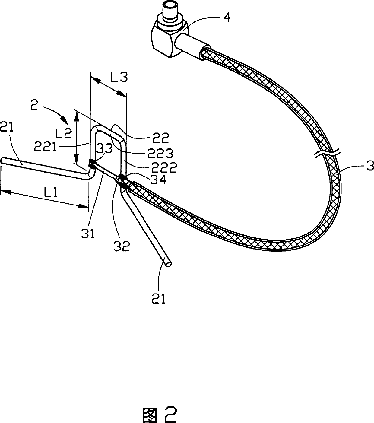
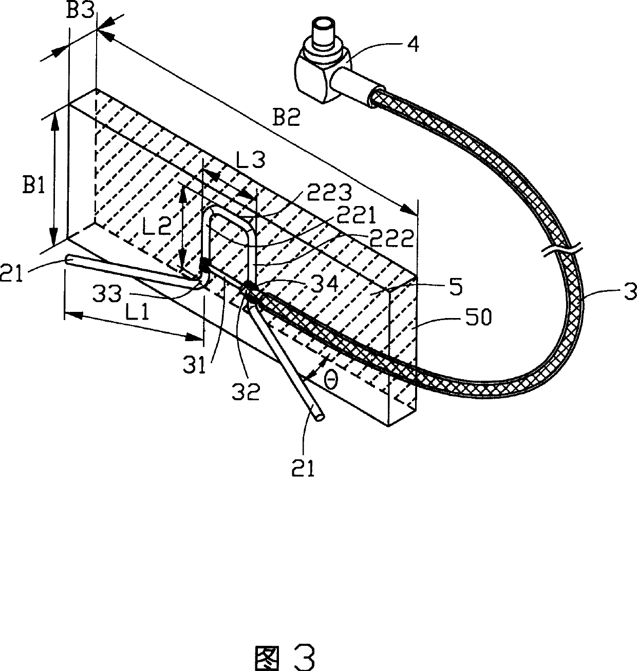
[0014] Referring to FIG. 2 , the antenna of the present invention includes an antenna body 2 and a feeder 3 , wherein the antenna body 2 includes a connector 22 and two metal arms 21 extending from two free ends of the connector 22 . The connector 22 includes a first side wall 221, a second side wall 222 and a top wall 223 connecting the first side wall 221 and the second side wall 222. One ends of the two side walls 222 protrude. In this embodiment, the two metal arms 21 extend outward from the plane where the connecting member 22 is located, and have an included angle θ with the plane where the connecting member 22 is located. The feeder 3 usually includes a first conductor and a second conductor. In this embodiment, the feeder 3 is a coaxial cable, which is composed of a core wire 31 and a shielding layer 32. The core wire 31 at one end of the coaxial cable is connected to the connector 22 The first side wall 221 of the connector 22 is welded to form a first connection poi...


PUM


Abstract

The antenna set inside some electronic equipment includes dipole antenna and feeder line, the dipole antenna includes connecting part with at least one first side wall and one second side wall and two metal arms, and the feeder line includes two conductors. The two metal arms extends separately beyond the first side wall and the second side wall and the two conductors are connected separately to the first side wall and the second side wall to form the first joint point and the second joint point. The said mode can simplify the connection between feeder line and the dipole antenna and thus the manufacture and assembly of the antenna.

Description

【Technical field】 [0001] The present invention relates to an antenna, in particular to an antenna placed in an electronic device and working under an ISM (Industry, Science, Medicine) frequency band. 【Background technique】 [0002] For electronic devices with communication receiving functions, with the trend of miniaturization and design simplification of electronic devices, there is a corresponding demand for miniaturization of the volume of various communication equipment including antennas. The planar inverted "F" antenna ( Planar Inverted-F Antenna (PIFA) is a commonly used small antenna suitable for communication terminals. Please refer to Fig. 1 for the prior art, which is a plane inverted "F" antenna, the plane inverted "F" antenna 1 includes a grounding sheet 11, a radiation sheet 12, a short circuit sheet 13 and a TEM (transverse electromagnetic wave) transmission line 14, The two ends of the shorting plate 13 are respectively welded on the ground plate 11 and the ...

Claims


Application Information

Patent Timeline
IPC IPC(8): H01Q1/24H01Q1/36
Inventor 蔡赐男沈祥辉戴新国郑昆德林宪助游杰超
Owner FOXCONN (KUNSHAN) COMPUTER CONNECTOR CO LTD
Why Eureka
Try Eureka