
Convertible vehicle

Inactive Publication Date: 2010-03-23
VALMET AUTOMOTIVE
View PDF12 Cites 2 Cited by
  • Summary
  • Abstract
  • Description
  • Claims
  • Application Information

AI Technical Summary

Benefits of technology

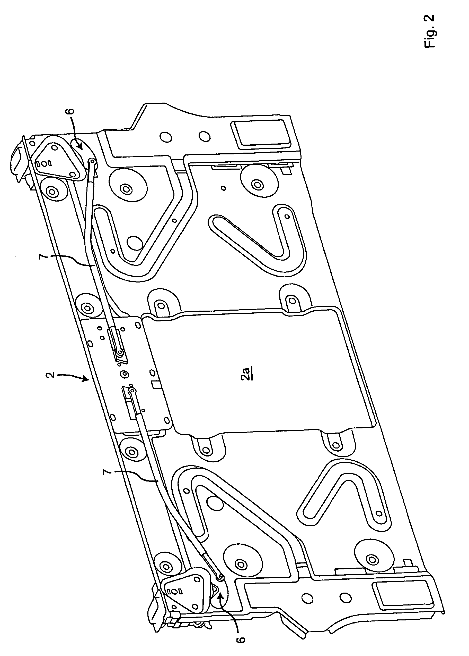
[0007]By this arrangement, a closure control of substantially reduced size can be provided. Since the drive includes a drive member disposed at least approximately in the transverse direction of the vehicle and in the plane of the force communicator, its projection into the trunk or roof stowage space is prevented. Since a transmission deflecting the direction of movement for a second force communicator can be moved via a coupling member movable in a straight line and parallel to the drive member and connected to a first force communicator, this transmission can also have an extent substantially parallel to the intermediate wall without far-projecting parts. In addition, the design is simplified due to the direct link of a first force communicator to the coupling member movable in a straight line.
[0009]If a plurality of coupling arrangements to a single transmission element are implemented for this purpose, the design is further simplified. Provided that at least one of the coupling arrangements is formed by a gear rack portion, a reliable force transmission can be achieved between parts moved in a linear straight line fashion and rotating parts.
[0010]A good accessibility for an emergency actuation is in particular achieved when the coupling arrangements are perpendicular to one another.
[0011]A reliable and space saving force transmission from the drive member results in a particularly advantageous manner when, for this purpose, a transmission member is arranged parallel to a piston of a drive member which can be pushed out and a gear is rotatable via the transmission element and a second transmission member movable in a straight line can be driven by it.

Problems solved by technology

In addition, a high construction effort results for conventional closure controls.

Method used


Image

  • Convertible vehicle
  • Convertible vehicle
  • Convertible vehicle

Examples


Embodiment Construction

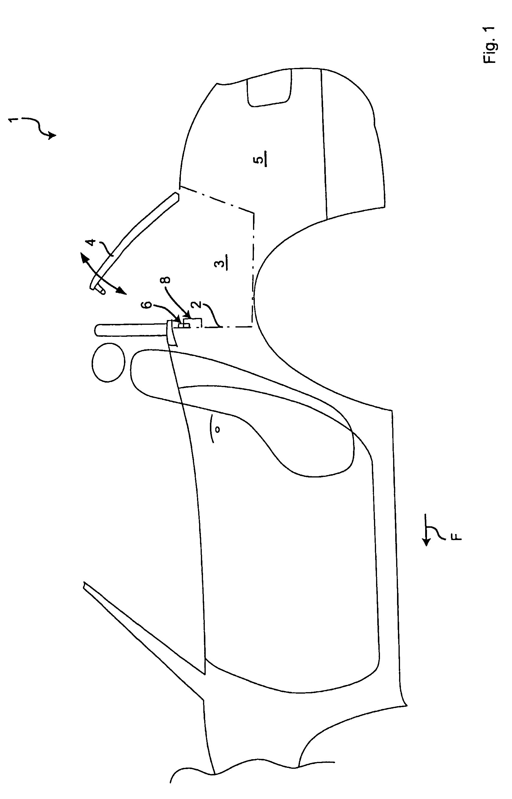
[0019]Referring to the figures, a convertible vehicle according to the invention is generally indicated at 1. The vehicle 1 includes a roof that is movable between a closed position extending over a passenger compartment and a stowed position disposed in a receiving space 3 located behind the passenger compartment.

[0020]The receiving space 3 is bounded at the front side with respect to a direction of travel “F” by an intermediate wall 2. optionally, the intermediate wall 2 may be provided with a recess 2a as a pass-through.

[0021]At the top, the receiving space 3 can be closed at least partly by a cover part 4. This is shown in a half open position in FIG. 1. The cover part 4 is pivotably hinged at its rear region to the car body 5, but may also be able to be opened and closed in a translatory manner or in a superimposed movement. It is also possible for the cover part 4 to be enlarged with respect to the drawing and, in a dual function, also to represent a trunk flap which can be op...


PUM


Abstract

The invention relates to a cabriolet vehicle having a roof that can be stored underneath a cover part in an open position, at least two displaceable engagement organs and an associated drive being provided to secure a closed cover part. The drive interacts with the engagement organs to transmit a driving force through a force transmission element having a component that extends in the transverse direction of the vehicle. A driven organ can lie in a transverse direction of the vehicle and generally on the same plane as the force transmission elements. In addition, a gear mechanism can be displaced by a rectilinear coupling organ that is connected to the force transmission element and runs parallel to the drive organ.

Description

REFERENCE TO RELATED APPLICATIONS[0001]This application is the United States national phase of Patent Cooperation Treaty application No. PCT / DE05 / 001539, filed Sep. 1, 2005, which claims priority to German patent application No. DE 10 2004 042 261.3-24, filed Sep. 1, 2004, the entire content of both of which is incorporated herein by reference.FIELD OF THE INVENTION[0002]The invention relates to a convertible vehicle comprising a roof stowable beneath a cover part closure control.BACKGROUND OF THE INVENTION[0003]A number of convertible vehicles are known in which a movable roof can be stowed in a roof receiving space beneath a cover part in an open position. For this purpose, the cover part is frequently pivoted to the car body in its rear region and has to be held at the car body for securing in its substantially horizontal closed position above the closed roof. Two engagement members, for instance rotary latches, arresting hooks or the like, disposed laterally outwardly can serve ...

Claims


Application Information

Patent Timeline
IPC IPC(8): B60J7/185B60J7/19
CPCB60J7/202E05B79/20E05C9/00E05B15/0086E05B81/20E05B81/90E05B81/10E05C9/041Y10S292/05E05B83/00
Inventor SELLE, HEINRICHHEIDTMANN, HERMANN
Owner VALMET AUTOMOTIVE
Learn More