Seal Device
a sealing device and sealing technology, applied in the direction of engine sealing, engine components, mechanical devices, etc., can solve the problems of neither promoting wear nor deteriorating the sealing ability
- Summary
- Abstract
- Description
- Claims
- Application Information
AI Technical Summary
Benefits of technology
Problems solved by technology
Method used
Image
Examples
example 1
OF THE PRESENT INVENTION
[0060]FIG. 7 represents a chart from the first test conducted under the following conditions in which temperatures at the close proximity of the first seal surface 5A and the second seal surface 15A were measured. Testing conditions of the first test are as follows.
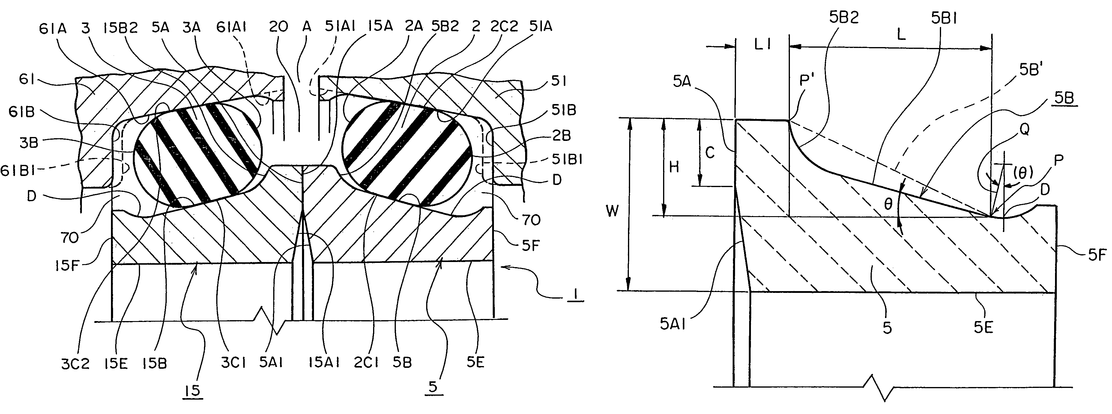
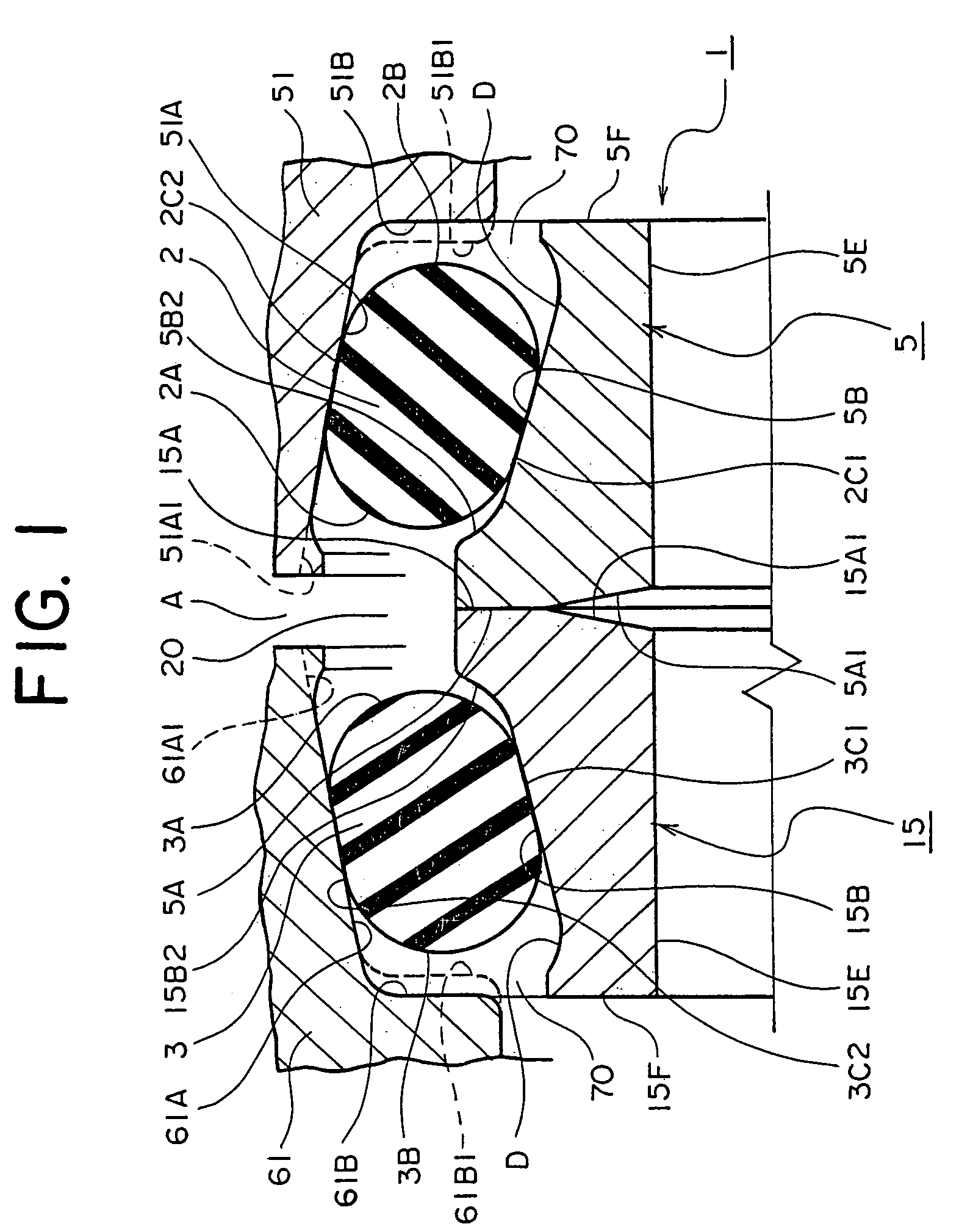
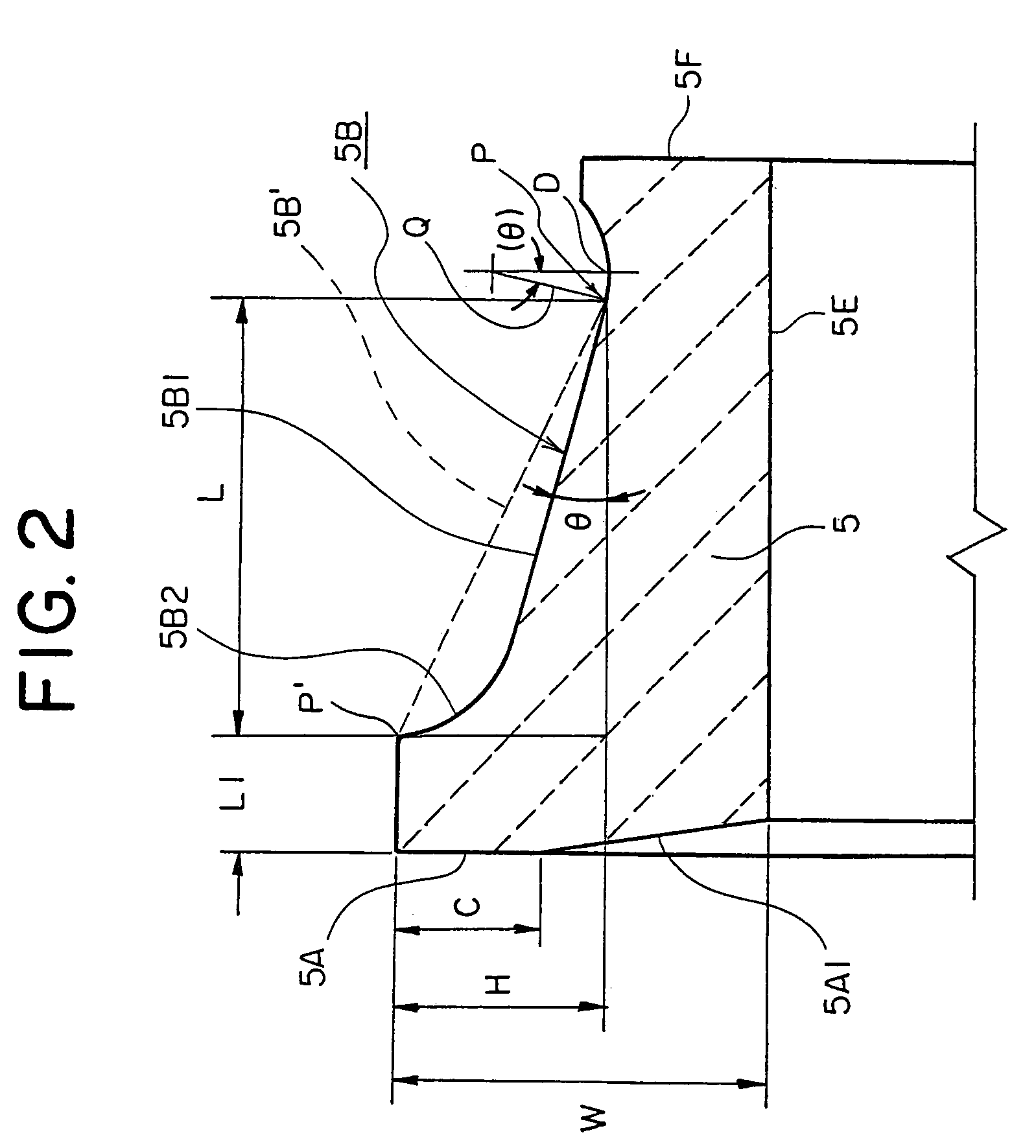
[0061]1) The first press urging surface 5B on the first seal ring 5 and the second press urging surface 15B on the second seal ring 15 are arranged in such a manner that H / L=0.35 in accordance with the form in FIG. 2.
[0062]2) Lubrication oil in the seal chamber 70 is gear oil #90 and is heated up by an oil heater.
[0063]3) Periphery speed of the first seal surface 5A is 0.6 m / s.
[0064]4) Testing duration is 50 hours in continuous operation.
[0065]Then the respective first seal surface 5A and the second seal surface 15A are forced a relative sliding motion to each other in which temperatures of at least two places were measured during sliding, a measurement spot U which is located in the proximity of o...
example 2
OF THE PRESENT INVENTION
[0068]FIG. 9 shows a chart from the first test conducted under the same conditions as the test of the example 1 in which temperatures at the close proximity of the first seal surface 5A and the second seal surface 15A were measured, except that
1) The first press urging surface 5B on the first seal ring 5 and the second press urging surface 15B on the second seal ring 15 are arranged in such a manner that H / L=0.50 in accordance with the form in FIG. 2.
[0069]The points used for measurement are the measurement point U shown in FIG. 6 of the first pressure urging surface 5B on the first seal ring 5 and of the second pressure urging surface 15B on the second seal ring 15, and additional measurement points which are located at symmetric locations, 180 degrees opposite on the circumference with respect to the measurement point U.
[0070]In the chart shown in FIG. 9, UT represents temperature measured at the measurement point U which is the upper plot shown in FIG. 6. ...
reference example 1
[0072]FIG. 11 shows a chart from the second test conducted under the same conditions as the test of the example 1 in which temperatures at the close proximity of the first seal surface 5A and the second seal surface 15A were measured, except that[0073]1) The first press urging surface 5B on the first seal ring 5 and the second press urging surface 15B on the second seal ring 15 are arranged in such a manner that H / L=0.67 in accordance with the form in FIG. 2 (similar form to the seal rings in FIG. 13).
[0074]The respective first seal surface 5A and second seal surface 15A are subjected to a relative sliding, and one measurement point U and another measurement point were used for measuring increasing temperatures thereat in which the point U is located at the close proximity of the outer circumference as shown in FIG. 6 and the other measurement point is located at the symmetrically opposite position by 180 degrees along the circumference with respect to the point U. The test result w...
PUM
 Abstract
Description
Claims
Application Information
 - R&D
- Intellectual Property
- Life Sciences
- Materials
- Tech Scout
- Unparalleled Data Quality
- Higher Quality Content
- 60% Fewer Hallucinations
Browse by: Latest US Patents, China's latest patents, Technical Efficacy Thesaurus, Application Domain, Technology Topic, Popular Technical Reports.
© 2025 PatSnap. All rights reserved.Legal|Privacy policy|Modern Slavery Act Transparency Statement|Sitemap|About US| Contact US: help@patsnap.com


