
Wireless local area network with clients having extended freedom of movement

a wireless network and client technology, applied in the field of wireless local area networks, can solve the problems of changing paradigms, unexpected and unpredictable market developments, disruptive technologies of wlan technology, etc., and achieve the effect of improving user mobility on wireless networks

Inactive Publication Date: 2010-03-16
SIEMENS CANADA LTD
View PDF22 Cites 123 Cited by
  • Summary
  • Abstract
  • Description
  • Claims
  • Application Information

AI Technical Summary

Benefits of technology

Enables continuous network connectivity for mobile devices beyond the range of the initial access point, using a second wireless network for seamless handoffs and maintaining connections without manual intervention, thus enhancing user mobility and network availability.

Problems solved by technology

Consequently, WLAN technology has been characterized as a disruptive technology.
In other words, WLAN technology may change paradigms and lead to unexpected and unpredictable market developments.
Currently however, there are three major limitations on WLAN technology: speed, range and security.
If after sending a request, however, the connection is lost prior to receiving a response, the response was lost.
Once reconnected, whether to the same or a different port and, even prior to arrival of the response, the response was lost and the request had to be sent anew.
Other wireless technologies, especially wireless cell phone technologies, provide a more or less suitable connection (albeit an expensive one) when an access point isn't readily available.
As wireless communications technology advances towards next generation higher speed communications, the performance of this type of alternate connection may become acceptable, but cost is still expected to be a barrier to exclusive use.
Furthermore, manually switching between cellular (or other wireless communications technology) and a lower cost wireless LAN connection is very disruptive.

Method used


Image

  • Wireless local area network with clients having extended freedom of movement
  • Wireless local area network with clients having extended freedom of movement
  • Wireless local area network with clients having extended freedom of movement

Examples


Embodiment Construction

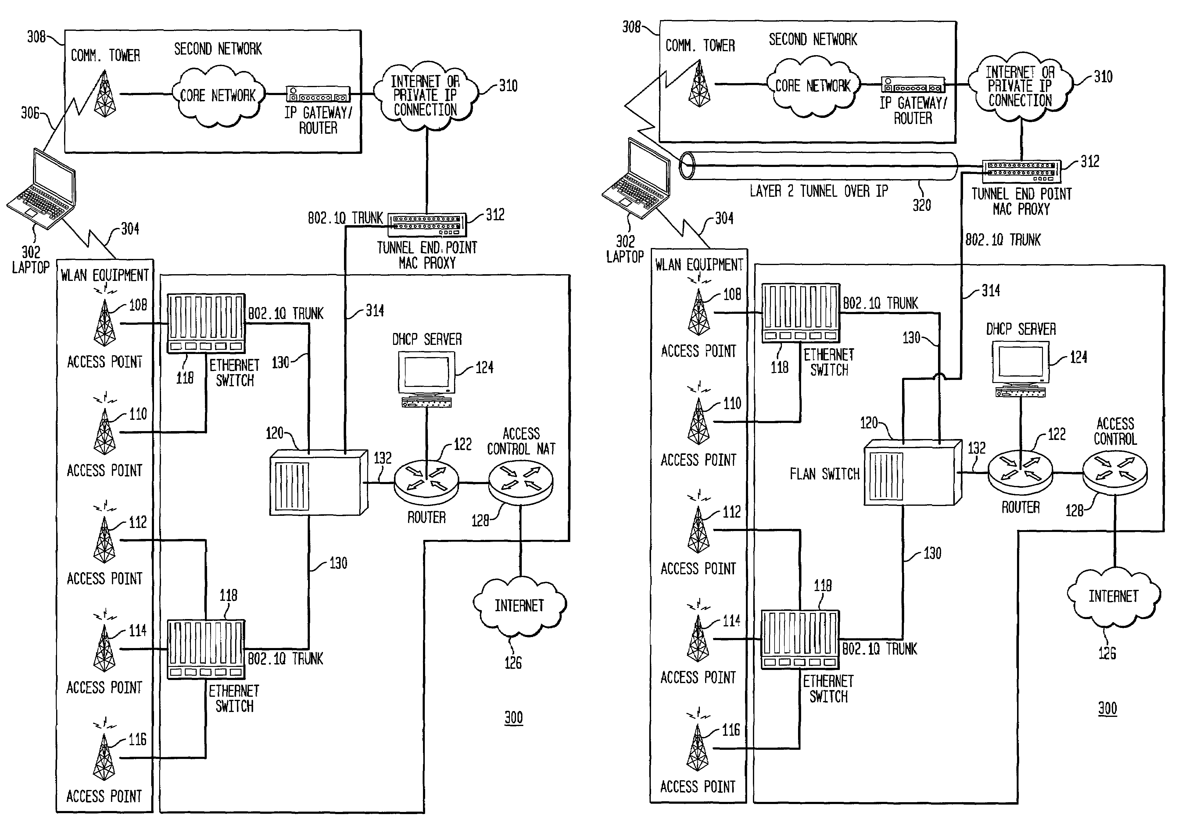
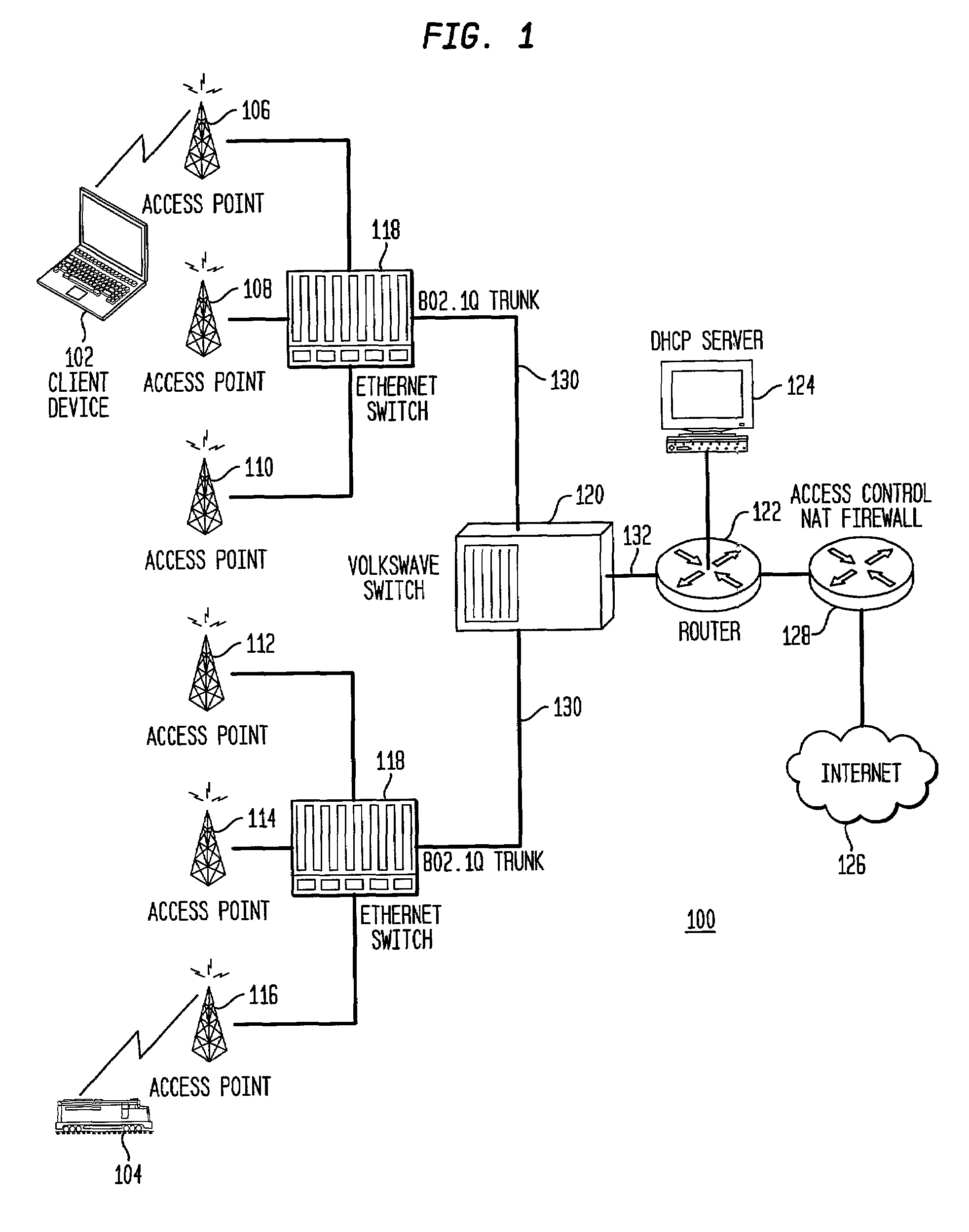
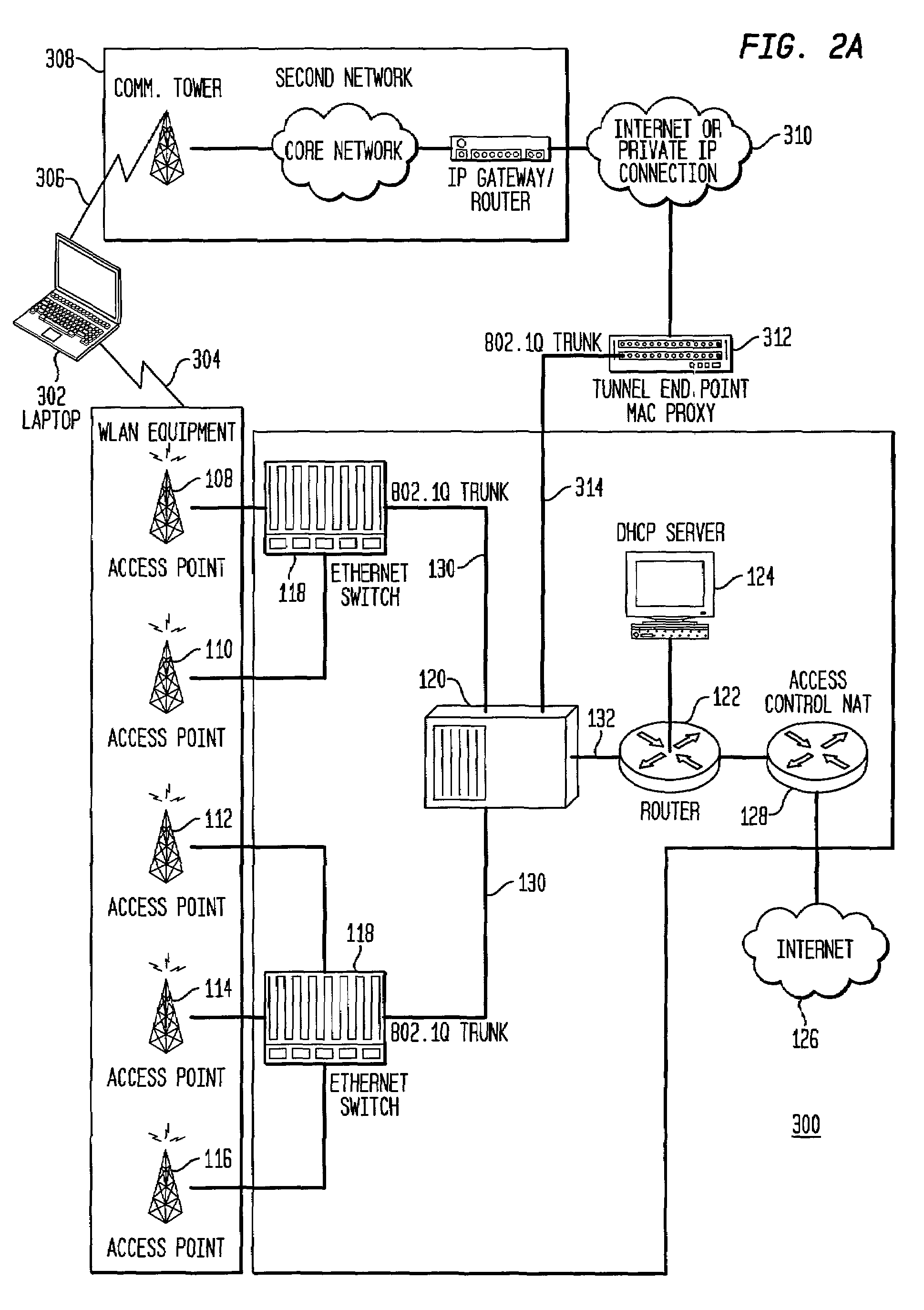
[0025]FIG. 1 shows an example of a free-form virtual local area network (FLAN) 100 with wireless access capability as described in U.S. patent application Ser. No. 10 / 140,629 entitled “LOCAL AREA NETWORK WITH WIRELESS CLIENT FREEDOM OF MOVEMENT” to Matthew G. Eglin, filed May 8, 2002, and assigned to the assignee of the present invention. Wireless clients / mobile stations connect to the FLAN 100 and, once connected, roam freely within the wireless coverage area, seamlessly swapping wireless connection from one access point to another access point as they roam. The present invention extends the wireless client roaming capability beyond the FLAN wireless coverage area for appropriately equipped wireless client devices.

[0026]Normally, wireless client devices or mobile stations (MS) 102, 104 are connected by wireless data links to one of numerous access points (APs) 106, 108, 110, 112, 114, 116. Examples of such mobile stations 102, 104 or wireless client devices may include what is know...


PUM


Abstract

A wireless virtual local area network (VLAN) and a device selectively connecting to the wireless VLAN over a second wireless network that may be independent of the wireless VLAN. The device is capable of connecting to at least the wireless VLAN and to the second wireless network. Wireless VLAN access points are each connected to an Ethernet aggregation switch, which is VLAN aware and matches client traffic from connected access points with access VLANs. A wireless VLAN switch maintains an association table between access VLANs and core VLANs. The second wireless network may be remotely connected over the Internet or a private network to a tunnel endpoint. The tunnel endpoint is connected to the VLAN switch, which uses the association table to manage free-form client traffic between connected devices and other mobile stations at access VLANs and appropriate core VLANs.

Description

RELATED APPLICATION[0001]The present application is related to U.S. patent application Ser. No. 10 / 140,629 entitled “LOCAL AREA NETWORK WITH WIRELESS CLIENT FREEDOM OF MOVEMENT” to Matthew G. Eglin, filed May 8, 2002, and assigned to the assignee of the present invention.BACKGROUND OF THE INVENTION[0002]1. Field of the Invention[0003]The present invention is related to a wireless local area network (WLAN) and more particularly, to a WLAN with connected wireless communication devices.[0004]2. Background Description[0005]The Institute of Electrical and Electronics Engineers (IEEE) wireless protocol designated 802.11b is an Ethernet local area network (LAN) variant. Ethernet technology has shown an amazing ability to adapt to new requirements, evolving from a simple 10 Mbps bus to gigabit full-duplex switched networks and to wireless LANs. Ethernet is well understood and there is a wealth of experience with cost reduction and integration of Ethernet devices. Some current Ethernet inter...

Claims


Application Information

Patent Timeline
Patent Type & Authority Patents(United States)
IPC IPC(8): H04W4/00G16H10/60H04L12/28H04L12/46H04W88/12
CPCG06Q50/24H04L12/2856H04L12/4633H04L12/4641H04W88/12G16H50/30G16H70/60G16H50/70H04L12/28H04L12/46H04W84/12
Inventor EGLIN, MATTHEW GEORGE
Owner SIEMENS CANADA LTD
Learn More