
Image recording system, image data resource apparatus, image recording apparatus, image processing method, and program

Inactive Publication Date: 2010-03-02
CANON KK
View PDF16 Cites 24 Cited by
  • Summary
  • Abstract
  • Description
  • Claims
  • Application Information

AI Technical Summary

Benefits of technology

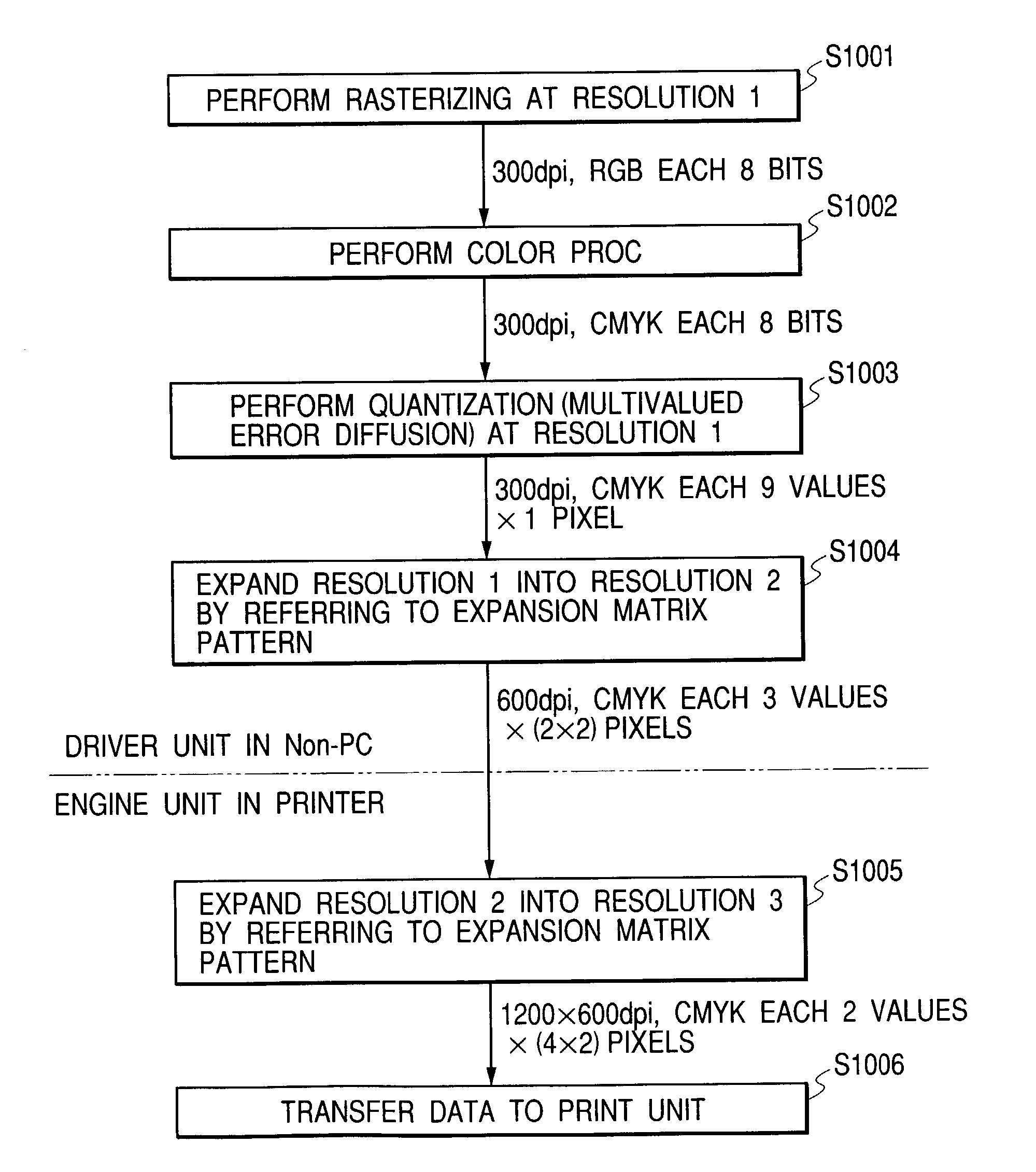
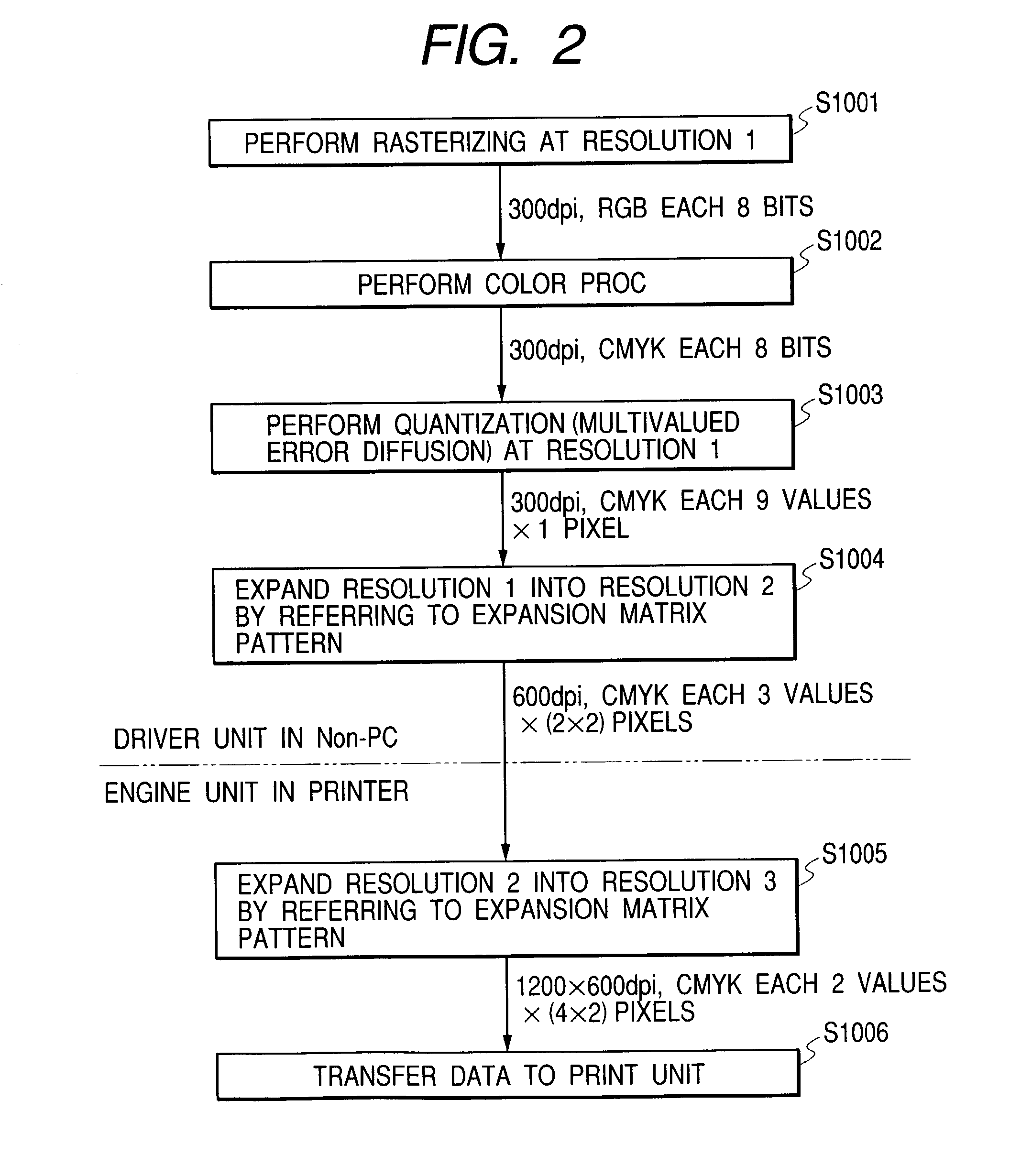
[0020]The present invention is made in consideration of the above problems, and an object thereof is to provide an image recording system, an image data resource apparatus, an image recording apparatus, an image processing method and a program for the image processing method which can reduce processing loads in an image processing unit, thus achieve an image output as maintaining image quality and speed even under the circumstances of no sufficient memory and no high-speed CPU, and further minimize loads in an engine unit as flexibly coping with various environments.

Problems solved by technology

For this reason, for example, there is a problem that a data processing time of a host computer (host apparatus, host PC (personal computer)) for transferring the image data to cause the recording apparatus (printer) to record the image, a transfer time of the image data from the host computer to the recording apparatus and the like are prolonged.
(1) Problems in Non-PC System
On the other hand, since the Non-PC system such as the WebTV™ system, the set-top box or the like does not necessarily have the large-capacity memory and the high-speed CPU as above, if the process to be performed by the printer driver on the PC is applied to this system as it is, the problem that the image quality and speed same as above cannot be maintained occurs.
Moreover, even if the above matrix recording method is intended to be applied to solve this problem, in fact, it is too various and uncertain to assume beforehand methods for expanding the matrix patterns corresponding to the operation environments in the various Non-PC systems and prepare the assumed methods in the engine unit of the printer, whereby the problem that the engine unit of the printer suffers from excessive loads occurs.
Therefore, it is thought that the above matrix recording method cannot be applied as a matter of fact.
Thus, although achieved on the printer driver of the PC, the process cannot be necessarily achieved at the resolution required by a user.
For this reason, the image output from the printer which can be achieved on the PC cannot be necessarily achieved on the Non-PC system.
In the worst case, the problem that it is impossible to perform the printing might occur.
(2) Problems in PD Printer System
As well as the Non-PC system, it is impossible in the controller unit of the PD printer system to expect the large-capacity memory and the high-speed CPU as provided in the PC because these parts remarkably raise the cost.
Thus, if the process to be performed by the printer driver on the PC is applied to this system as it is, the problem that the image quality and speed same as above cannot be maintained occurs.
As a matter of fact, in the various PD printer systems which are currently commercialized, the products each of which can maximally utilize the print speed of the engine unit of its printer are few due to the problem of processing loads in the controller unit.
However, this is the excessive specification for a simple body of this base printer, whereby the problem that such a specification might come to affect a program storage unit and the like occurs.
Particularly, in a case where the base printer has been already commercialized, the PD printer on which the controller unit is added cannot achieve in this controller unit the processing speed at the data resolution receivable by that printer, whereby the problem that the print speed inherent in the engine unit cannot be sufficiently satisfied occurs.
In summary, the system, which is expected to be further popularized in future, for outputting the image data from the devices other the PC to the printer roughly has the following two problems, that is, (1) if the process of the printer driver performed on the PC is directly applied as it is, the image quality and the speed (general speed including image processing speed, data transfer speed, and print speed) cannot be maintained because the load of the image processing unit in the printer increases, and (2) the operation environments for applying the matrix recording method to solve the above problem (1) are various, whereby it is difficult to entirely contain the appropriate matrix recording method within the printer engine.

Method used


Image

  • Image recording system, image data resource apparatus, image recording apparatus, image processing method, and program
  • Image recording system, image data resource apparatus, image recording apparatus, image processing method, and program
  • Image recording system, image data resource apparatus, image recording apparatus, image processing method, and program

Examples


first embodiment

[0040]First, the structure of an information processing system according to the first embodiment of the present invention will be explained with reference to FIG. 1. FIG. 1 is the block diagram showing the structure of the information processing system according to the first embodiment. The information processing system includes a Non-PC 100, a bidirectional interface (I / F) 200, and an image output apparatus 300 consisting of a printer and the like. Here, it should be noted that the image output apparatus 300 may be called a printer 300 hereinafter. The Non-PC 100 and the image output apparatus 300 are connected with each other through the bidirectional I / F 200. The Non-PC 100 is the apparatus such as a WebTV™ system, a set-top box or the like which does not use a PC, and a printer driver 110 is installed as the memory of the Non-PC 100. Moreover, the image output apparatus 300 includes an engine unit 310 which performs an image process and a print unit 320 which performs printing o...

second embodiment

[0061]In the above first embodiment of the present invention, the quantization resolution in the printer driver, the transfer resolution from the printer driver to the engine unit of the printer, and the print resolution are all the same (in common) for each of the used colors. On the other hand, it will be explained in the second embodiment a case where a quantization resolution in a printer driver, a transfer resolution in data transfer from the printer driver to an engine unit of a printer, and a print resolution are different for each color. In the engine unit of the printer according to the present embodiment, five-valued data of 600 dpi is received in relation to C and M, and the received data is expanded into four pixels of 1200 dpi and binary-recorded. On the other hand, binary data of 600 dpi is received for Y and K, the received data is binary-recorded for one pixel of 600 dpi as it is.

[0062]Next, a PD printer according to the second embodiment will be explained with refer...

third embodiment

[0091]Although the case where the data output form to the printer engine and the data expansion by the printer engine into the recording data are performed by utilizing the known matrix recording method is explained in the above first and second embodiment, other methods will be explained in the third embodiment. That is, in the present embodiment, a case to assume, as a printer engine of a printer, a printer engine which receives multivalued data of 600 dpi and discharges a large number of ink droplets of levels 0 to n′ according to the multivalued data of 0 to n′ into the same pixel of 600 dpi to form an image will be explained, and also a case to assume, as a host PC, a device which transfers the multivalued data of 600 dpi to the printer engine will be explained. In the printer engine of such a type, the number of any of levels 0 to n′ in relation to each pixel applied to the engine unit does not need to coincide with the number of ink droplets actually discharged to each pixel....


PUM


Abstract

A printer driver of a Non-PC controls to quantize image data at quantization resolution (resolution 1), convert the quantized data into data resolution (resolution 2), and then transfer the data of the data resolution to an engine unit of an image output apparatus. The engine unit converts the data resolution of the received data into recording resolution (resolution 3) for a recording medium. Here, the quantization resolution is set to be lower than the data resolution. Thus, processing loads in the image processing unit can be reduced, whereby it is possible to provide image output capable of maintaining image quality and speed even under the circumstance that there is no sufficient memory and high-speed CPU, and to provide image output capable of maintaining image quality and speed according to a matrix recording method flexibly coping with various environments and minimizing the load in the engine unit.

Description

BACKGROUND OF THE INVENTION[0001]1. Field of the Invention[0002]The present invention relates to an image recording system, an image data resource apparatus, an image recording apparatus, an image processing method and a program for the image processing method each of which uses a matrix pattern process to expand image data into recording data corresponding to a predetermined dot matrix and record an image on a recording medium by using plural recording elements, and more particularly, to an image recording system, an image data resource apparatus, an image recording apparatus, an image processing method and a program for the image processing method each of which can provide a high-quality image at high speed.[0003]2. Related Background Art[0004]Conventionally, in a recording apparatus which records an image on a recording medium such as a paper or the like, it is intended to increase resolution of image data because a high-quality image is demanded. However, according as the resolu...

Claims


Application Information

Patent Timeline
IPC IPC(8): G06K15/02B41J2/525B41J5/30G06F3/12H04N1/41H04N1/46H04N1/60H04N1/64
CPCH04N1/648B41J2/01
Inventor KATO, MASAOWATANABE, TOMOYUKIYAMADA, AKITOSHI
Owner CANON KK
Learn More