Liquid droplet discharging apparatus and head with liquid droplet guides
a technology of liquid droplet and guide, which is applied in the direction of printing, etc., can solve the problems of hindering the accurate landing of liquid droplets on target positions, difficult to allow liquid droplets to accurately land on target positions, and insufficient stability of straight flight, so as to facilitate the landing of liquid droplets, facilitate the application of rotational force, and high quality
- Summary
- Abstract
- Description
- Claims
- Application Information
AI Technical Summary
Benefits of technology
Problems solved by technology
Method used
Image
Examples
first embodiment
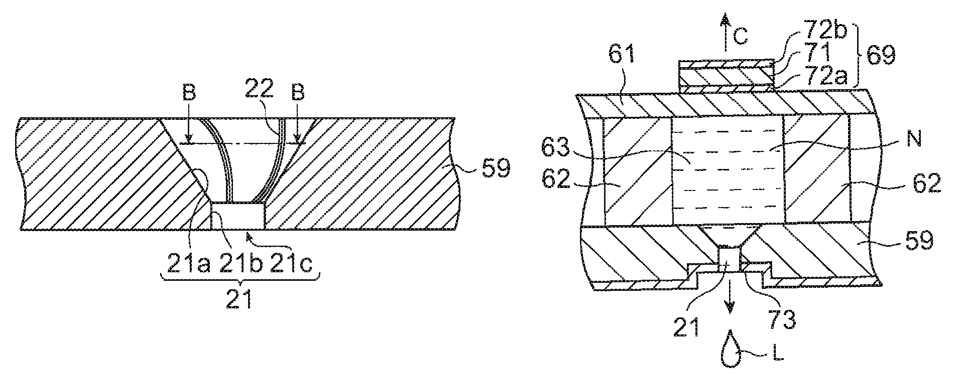
[0118]A first embodiment of the invention describes a liquid droplet discharging head in which a nozzle as a penetrating portion includes a spiral narrow groove used as a liquid droplet guiding portion. The liquid droplet guiding portion means a physical structure such as a groove formed by carving a surface of the penetrating portion formed in a substrate or a protruded portion formed on the substrate, with a chemical structure such as lyophilic and lyophobic regions formed on the surface of the penetrating portion. Any of the structures can serves to help a liquid droplet pass through the penetrating portion.
[0119]First, a description will be given of a structure of the liquid droplet discharging head incorporated in a liquid droplet discharging apparatus, according to exemplary embodiments of the invention.
[0120]FIGS. 12A and 12B partially show a main part of the liquid droplet discharging head. FIG. 12 is a schematic perspective view of the main part thereof and FIG. 12B is a sc...
second embodiment
[0146]A second embodiment of the invention describes a liquid droplet discharging head including a linear groove formed at a nozzle section of the nozzle plate. The linear groove is formed on the first penetrating portion.
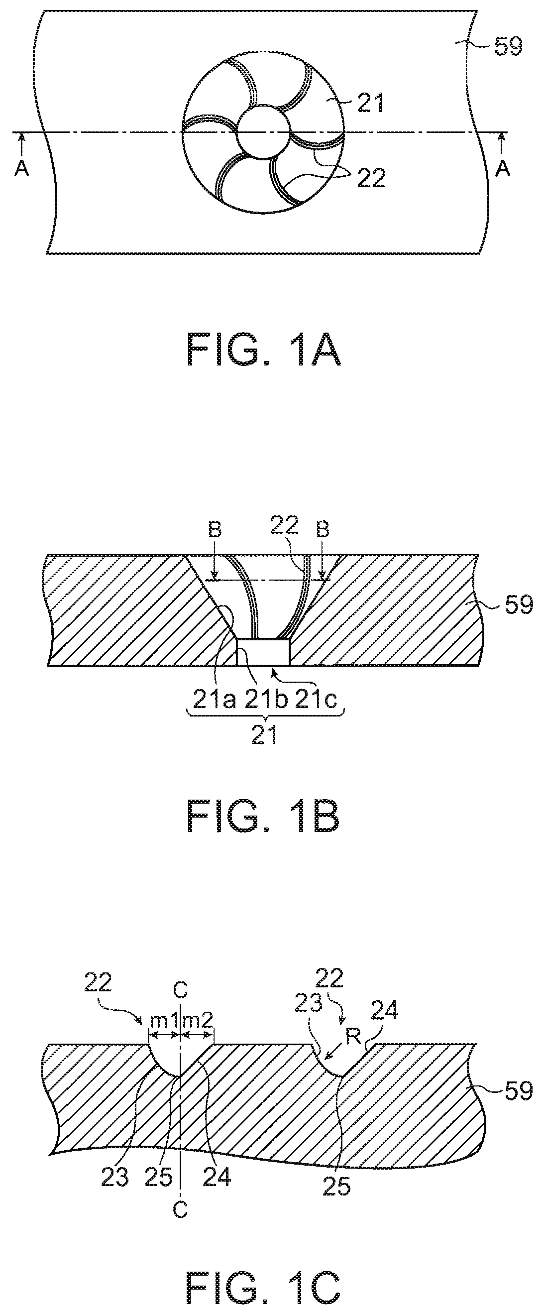
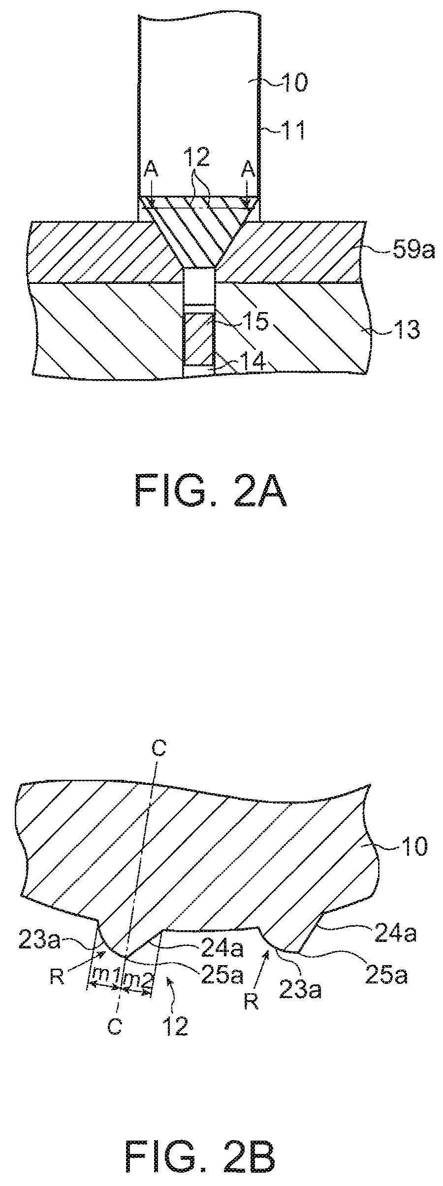
[0147]FIGS. 3A to 3C schematically show an example of the nozzle plate included in the liquid droplet discharging head according to the second embodiment. FIG. 3A is a plan view of the example thereof, FIG. 3B is a sectional view of the example thereof taken along a line A-A of FIG. 3A. FIG. 3C is a sectional view of the example thereof taken along a line B-B of FIG. 3B. FIGS. 4A and 4B illustrate a method for manufacturing the nozzle plate included in the liquid droplet discharging head. FIG. 4A is a schematic view of the nozzle plate and FIG. 4B is a sectional view thereof taken along a line A-A of FIG. 4B. Referring to FIGS. 3A to 3C and 4A and 4B, a description will now be given of the nozzle plate included in the liquid droplet discharging head according to th...
third embodiment
[0159]A third embodiment of the invention describes a liquid droplet discharging head having patterns with different wettabilities at the nozzle section of the nozzle plate. Those patterns having different wettabilities are formed at the first penetrating portion.
[0160]FIGS. 5A and 5B schematically show an example of the nozzle plate included in the liquid droplet discharging head according to the third embodiment. FIG. 5A is a plan view of the example thereof and FIG. 5B is a sectional view taken along a line A-A of FIG. 5A. FIGS. 6A and 6B illustrate a method for manufacturing the nozzle plate included in the liquid droplet discharging head. FIG. 6A is a schematic view of a photomask and FIG. 6B shows a state in which the photomask is placed on a nozzle plate material. FIG. 7 shows a flowchart of processes performed in the manufacturing method of the nozzle plate included in the liquid droplet discharging head. Referring to FIGS. 5A to 7, a description will be given of the nozzle ...
PUM
 Abstract
Description
Claims
Application Information
 - R&D
- Intellectual Property
- Life Sciences
- Materials
- Tech Scout
- Unparalleled Data Quality
- Higher Quality Content
- 60% Fewer Hallucinations
Browse by: Latest US Patents, China's latest patents, Technical Efficacy Thesaurus, Application Domain, Technology Topic, Popular Technical Reports.
© 2025 PatSnap. All rights reserved.Legal|Privacy policy|Modern Slavery Act Transparency Statement|Sitemap|About US| Contact US: help@patsnap.com


