
Room heating system

a technology for heating systems and rooms, applied in the field of room heating systems, can solve problems such as regulation problems, and achieve the effect of no additional energy consumption

Inactive Publication Date: 2010-03-02
DANFOSS AS
View PDF15 Cites 5 Cited by
  • Summary
  • Abstract
  • Description
  • Claims
  • Application Information

AI Technical Summary

Benefits of technology

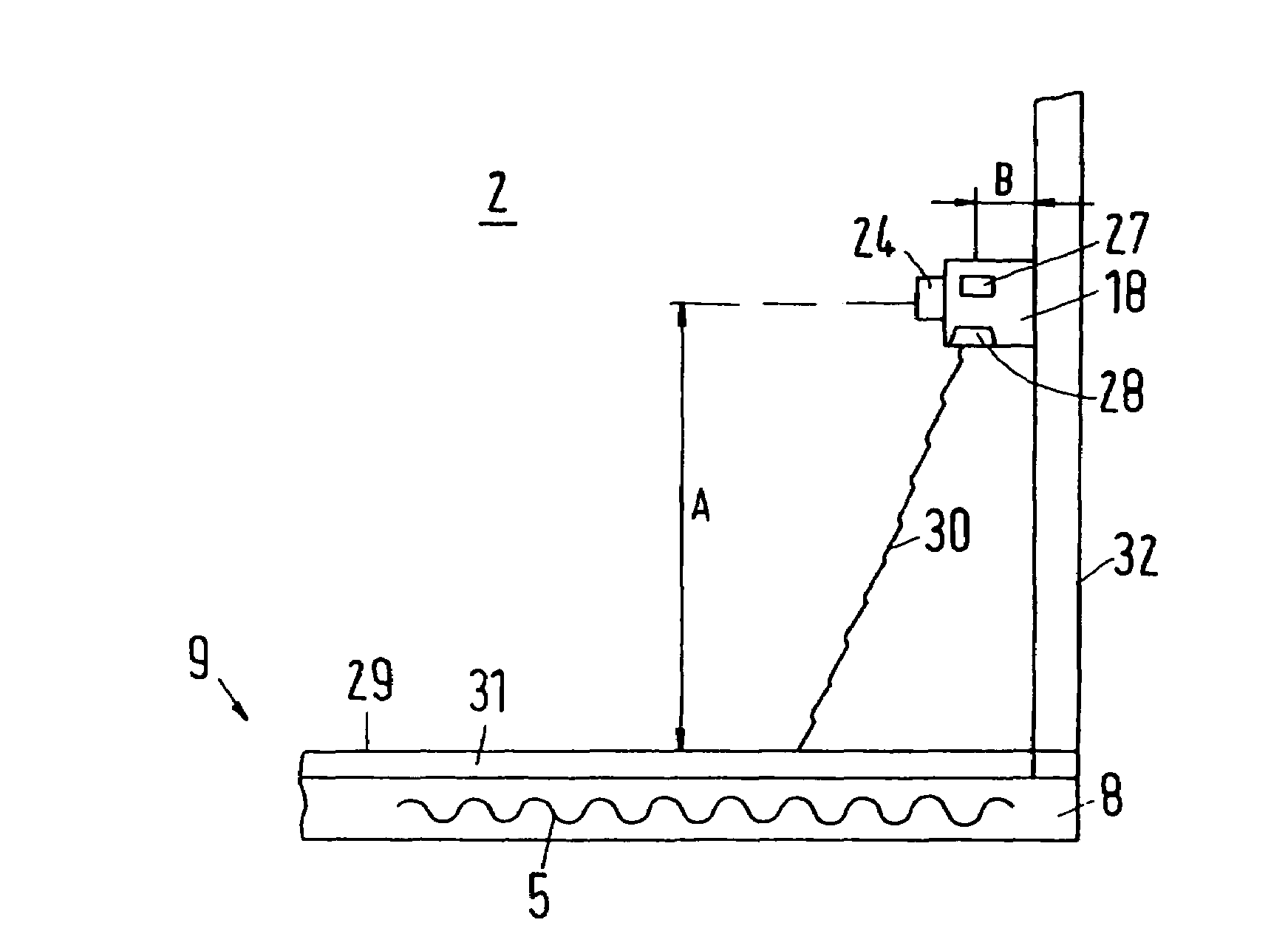
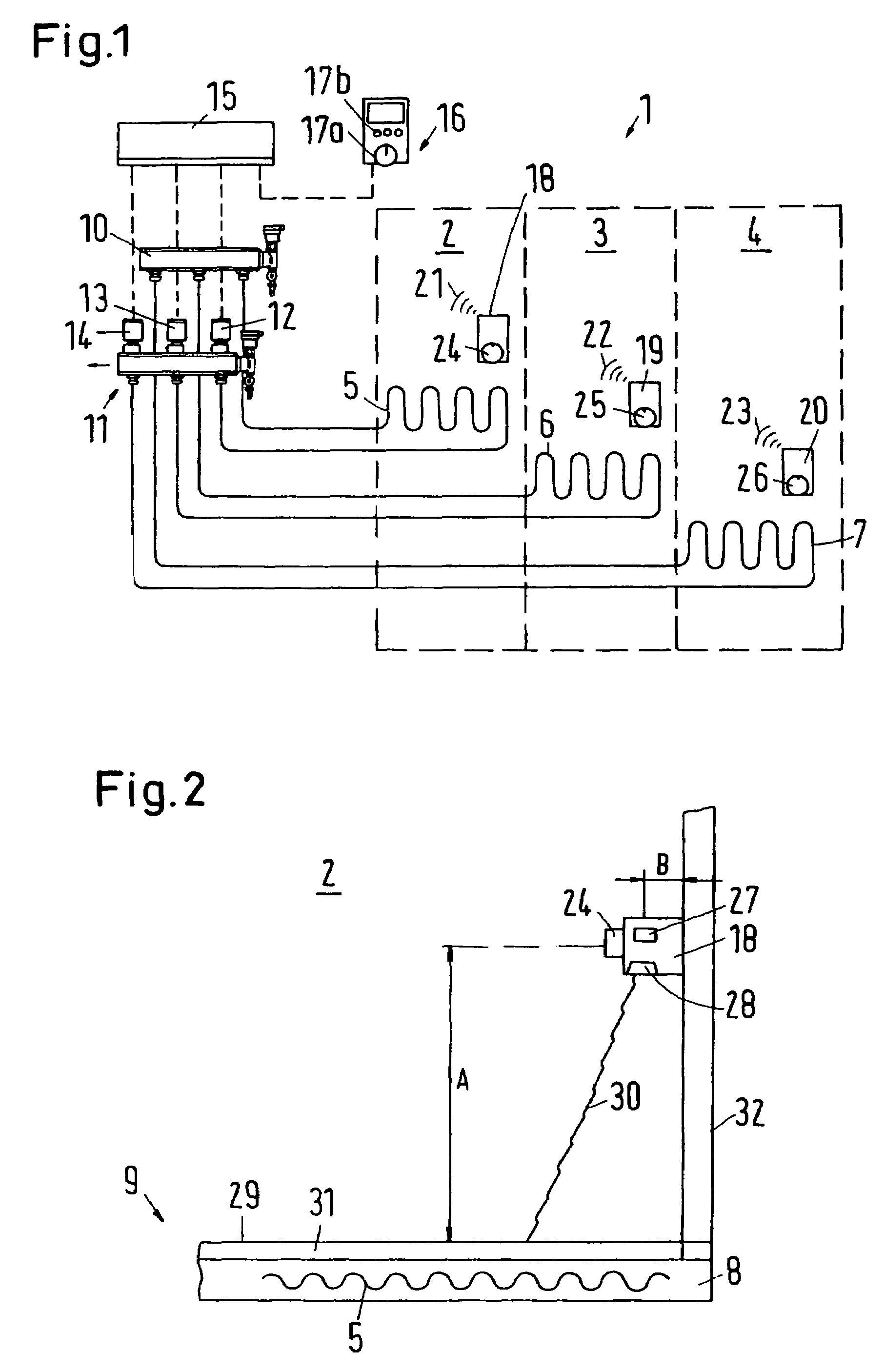
[0009]Thus, this surface temperature sensor is a “remote sensor”, which can be located at a distance to the floor. This will eliminate practically all the problems involved in bedding the temperature sensor in the floor. Further, the room thermostat is combined with the surface temperature sensor, so that a compact component is achieved. This component is only negligibly or not at all larger than a traditional room thermostat, so that for the user of the room changes are practically not noticeable. Further, also the communication between the regulating unit and the individual sensor, that is, the room air sensor and the surface temperature sensor, is simplified. When these two sensors are located next to each other, it is possible that one single transmission path to the regulating unit will be sufficient. The location of the room thermostat merely has to be chosen so that on the one hand the room thermostat can determine the room air temperature; on the other hand, however, also the surface temperature of the floor. This leaves more freedom for decorating the room, as the structural measures to be taken when locating the surface temperature sensor require substantially less efforts than bedding the temperature sensor in the floor.
[0011]Preferably, the room thermostat is wirelessly connected with the regulating unit. Thus, no mounting of wires is required to ensure the communication between the room thermostat and the regulating unit. On the contrary, the wireless connection can take place via electromagnetic waves, for example, radio or light. This gives even more flexibility for locating a room thermostat in a room, that is, changes in decorating can be compensated very quickly. It is merely required that the surface temperature sensor can “see” the floor, that is, can perform measuring over a certain distance.
[0014]Preferably, the room thermostat is located at a height in the range of 1.2 to 1.8 m over the floor. In this height, the room thermostat has the possibility of determining the room air temperature on the one side and the surface temperature of the floor on the other side with a sufficient accuracy, so that the temperature control in the room can be performed with the required reliability.
[0018]It may be advantageous that the room thermostat only transmits surface temperature values to the regulating unit, when a medium surface temperature value changes by more than a predetermined value over a predetermined period. For example, four measurings can be made over a period of 15 to 30 minutes. Only when the medium value increases or decreases, this change is transmitted to the regulating unit. Thus, short-term influences, for example from sun radiation, people or animals in the room, are absorbed in such a manner that they cause no additional energy consumption.

Problems solved by technology

However, with such a location, some regulation problems occur.
Due to the inertia of the floor, delays occur in the measuring, so that a regulation takes place too late, which causes an overshoot.

Method used


Image

  • Room heating system
  • Room heating system

Examples


Embodiment Construction

[0022]FIG. 1 shows a schematic view of a heating system 1 with three rooms 2, 3, 4, each being provided with a floor heating system 5 to 7. In the present case, each floor heating system 5 to 7 is made as a heating hose, that is, a pipe fitted in a meander-shape, which is fitted in the plaster 8 (FIG. 2) of a floor 9. A heat carrying fluid, for example hot water, then flows through these floor heating systems 5 to 7.

[0023]The supply of the floor heating systems 5 to 7 takes place via an inlet connector, to which the floor heating systems 5 to 7 are connected. The control of the heat carrying fluid flowing through the floor heating systems 5 to 7 occurs via a control module 11, to which the floor heating systems 5 to 7 are connected. For each floor heating system, the control module 11 has a controllable valve 12 to 14. Depending on the released opening degree of the valves 12 to 14, a smaller or larger amount of the heat carrying fluid is flowing through the floor heating systems 5 ...


PUM


Abstract

A room heating system includes a heatable floor having a floor heating system, and a room thermostat having a room air sensor and being connected with a regulating unit for the floor heating system. The temperature control in a room is improved by providing the room thermostat with a surface temperature sensor, which determines a temperature on the surface of the floor from a distance.

Description

FIELD OF THE INVENTION[0001]The invention concerns a room heating system with a heatable floor having a floor heating system, and a room thermostat having a room air sensor and being connected with a regulating unit for the floor heating system.BACKGROUND OF THE INVENTION[0002]Such a room heating system is, for example, disclosed in the company brochure “Wireless regulation for floor heating” of Danfoss A / S, No. VD.78.K3.02, January 2002. The room thermostat measures the room temperature, and in dependence of the room temperature influences the floor heating system so that the temperature of the room air can be kept substantially constant.[0003]The floor heating system can have different embodiments. Commonly known are, for example, floor heating systems working with a heat carrying medium, for example hot water. In this case, the regulating unit influences the flow of this heat carrying medium through the floor. The floor then acts as heat exchanger, which supplies the heat from th...

Claims


Application Information

Patent Timeline
Patent Type & Authority Patents(United States)
IPC IPC(8): G05D23/12F24D19/00
CPCF24D19/1015F24D3/12Y02B30/00
Inventor JOERGENSEN, LASSEDAM, LARSHANSEN, JESPER BRUHN
Owner DANFOSS AS
Learn More